[0005] The injector of the invention having the characteristics recited in claim 1 offers the
advantage over the prior art that the existing short path through the recesses and relief grooves can be lengthened because of the offset of the recesses and relief grooves, and as a result the frictional forces which counteract an
extrusion of the sealing ring material through the recesses and relief grooves can be increased considerably. In other words, the existing
direct path is blocked, and a detour is created, which in combination with the small flow cross sections in the region of the detour, in other words between a recess and the adjacent relief groove, counteracts
extrusion of the sealing ring material. The passage of the leak fuel flow continues to remain assured, and at the same time its flow velocity is advantageously reduced by the offset arrangement in the circumferential direction of the relief grooves and recesses. The injector of the invention furthermore has a support ring of sturdy construction, since the weakening zones formed by the relief grooves and the recesses do not coincide, and excessive motions in the region of the recesses, which are suspected to be one of the causes for extrusion of the sealing ring material, are avoided.
[0006] By the disposition of the recesses and relief grooves in accordance with the invention, the support ring has a material thickness in the region of the recesses that is greater, by the groove depth of the relief grooves, compared to the prior art. As a result, the lower edges of the recesses come closer to the housing wall of the injector, which in turn in this region results in smaller gap cross sections, which also counteract any extrusion.
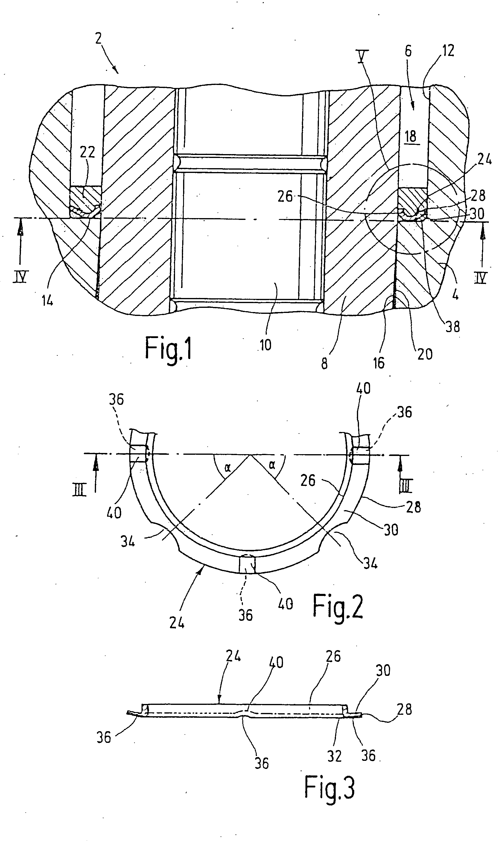
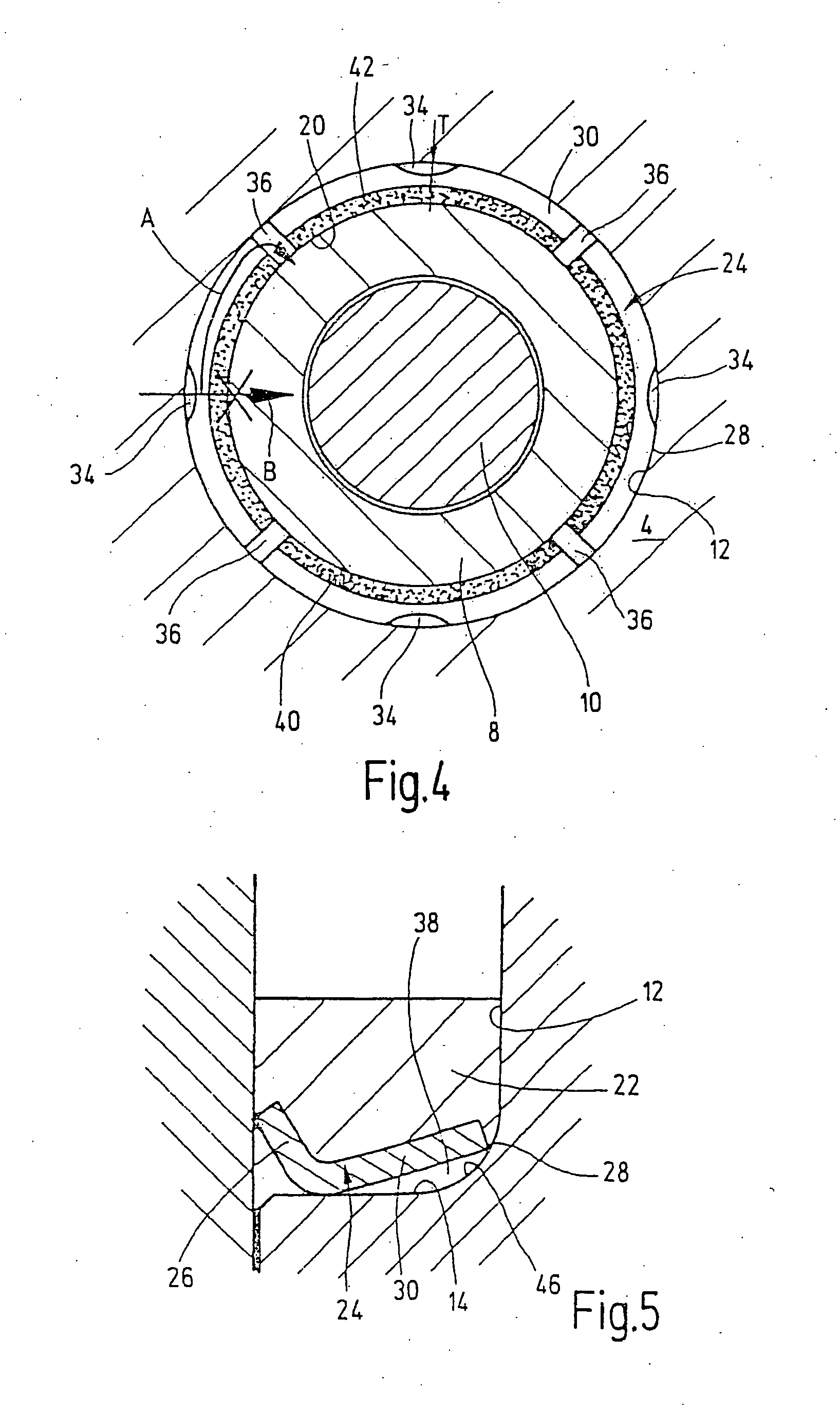
[0007] In a preferred feature of the invention, it is provided that the relief grooves and the recesses are offset from one another in such a way that one recess each is located between two relief grooves adjacent to one another in the circumferential direction, while conversely, one relief groove each is disposed between two recesses adjacent to one another in the circumferential direction, in both cases preferably in the middle.
[0008] A further preferred feature of the invention provides that the support ring, as before, has a total of four recesses, disposed at a spacing of 90° in the circumferential direction, and four relief grooves, also disposed at a spacing of 90° in the circumferential direction, in order to assure an adequate flow cross section for the leak fuel flow, but that the relief grooves are disposed at an angular spacing of 45° from the recesses, and vice versa, in order to create the longest possible detours between adjacent relief grooves and recesses.
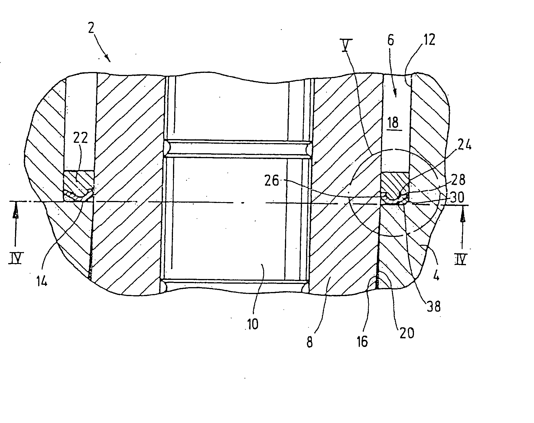
[0010] In a further preferred feature of the invention, the cross-sectional shape of the annular shoulder of the stepped bore and the cross-sectional shape of the support ring are advantageously adapted to one another in such a way that the support ring, between the recesses, rests with its outer circumferential edge essentially sealingly against a part, located above the annular shoulder, of the inner wall of the stepped bore and, between the relief grooves, rests with parts of its underside sealingly against the annular shoulder of the stepped bore. These parts of the underside that rest sealingly against the annular shoulder preferably border on the valve element and do not extend over the
full width of the support ring, so that flow conduits extending radially outward from the sealingly contacting parts between the annular shoulder and the underside of the support ring in its circumferential direction remain open with a small flow cross section and establish a communication between the recesses and relief grooves. The flow conduits are preferably embodied in the underside of the support ring, but they may also be embodied as an annular groove in the annular shoulder. The flow cross section of these flow conduits is expediently essentially equivalent to that of the relief grooves and the recesses.

