

Manufacturing straight bevel gears
a straight bevel gear and gear head technology, which is applied in the manufacture of gear teeth, gear teeth, gear-teeth manufacturing apparatus, etc., can solve the problems of time-consuming repositioning of work heads or tool heads by 180°, inability to lengthwise crown, and inability to leave extra metal at the tooth ends
- Summary
- Abstract
- Description
- Claims
- Application Information
AI Technical Summary
Problems solved by technology
Method used
Image

Examples
Embodiment Construction
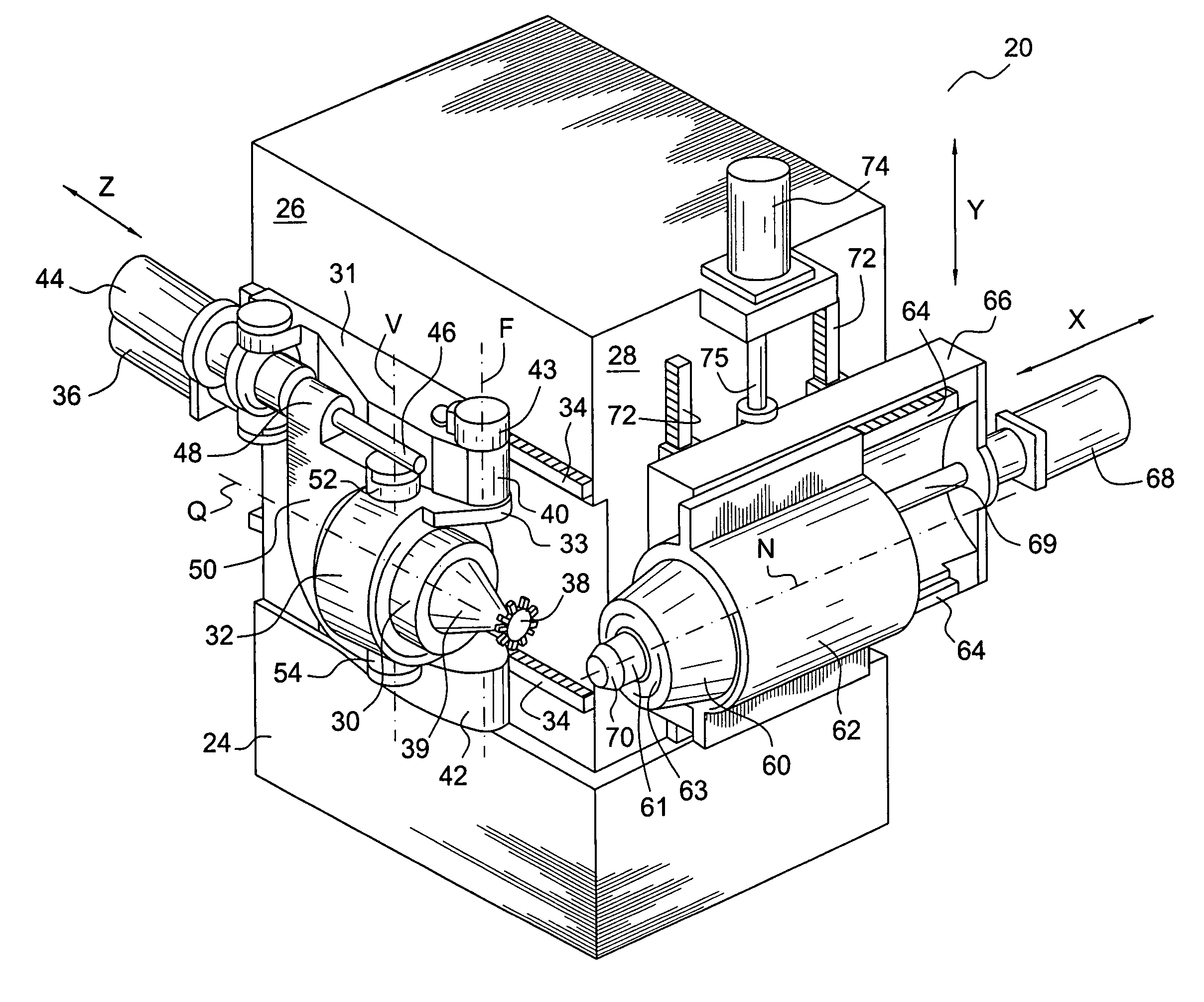
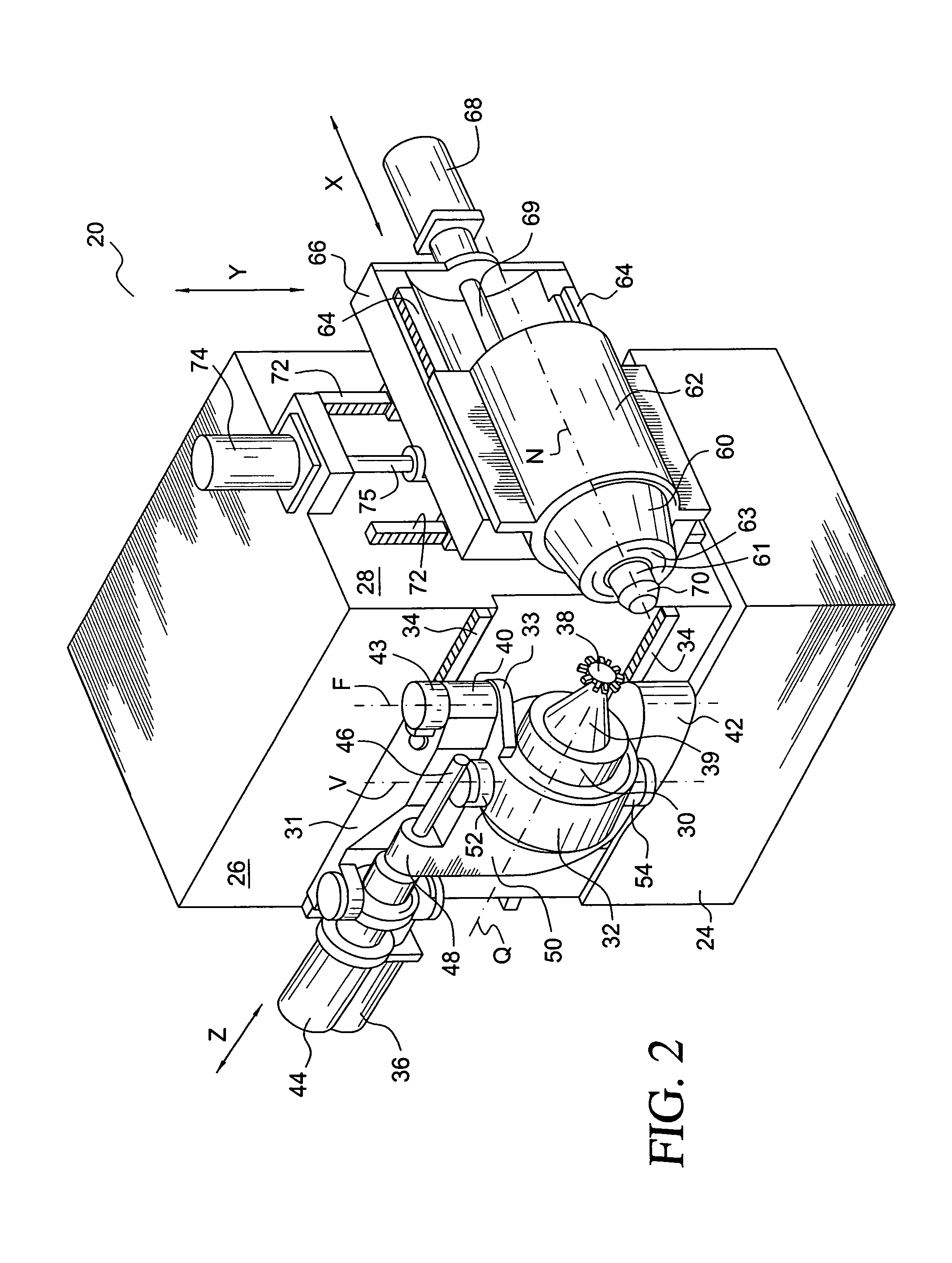
[0015]The details of the present invention will now be discussed with reference to the accompanying drawings which represent the invention by way of example only. In the drawings, like components will be referred to by the same reference numbers. Although the preferred embodiments will be discussed with reference to straight bevel gears, the present invention is not limited thereto but is intended to include similar types of toothed members, such as, for example, skew bevel gears, face couplings and splined shafts.
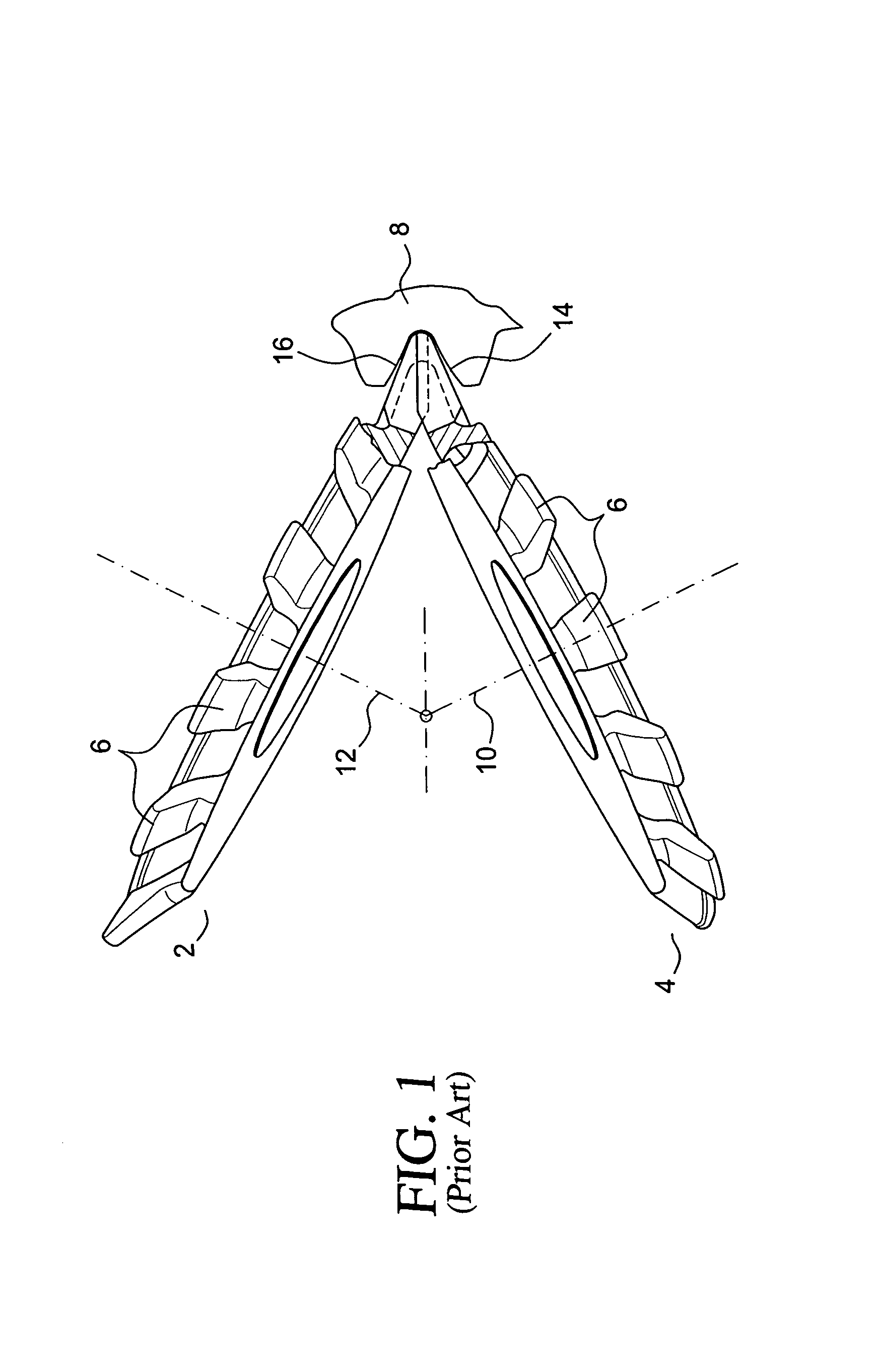
[0016]FIG. 1 illustrates the prior art arrangement of a pair of inclined rotary disc cutters 2, 4 (commonly referred to and upper and lower cutters) having cutting blades 6 for cutting a tooth slot in a workpiece 8. Cutter 2 is rotatable about axis 12 and cutter 4 is rotatable about axis 10. In a generating process on a conventional mechanical cradle-style machine, the inclined cutters 2, 4 are usually fed into the workpiece to a predetermined depth and a generating roll o...
PUM
| Property | Measurement | Unit |
|---|---|---|
| angle | aaaaa | aaaaa |
| root angle | aaaaa | aaaaa |
| mass | aaaaa | aaaaa |
Abstract
Description
Claims
Application Information