Method for thermal tomography of thermal effusivity from pulsed thermal imaging

Active Publication Date: 2008-04-29
UCHICAGO ARGONNE LLC
View PDF8 Cites 35 Cited by
  • Summary
  • Abstract
  • Description
  • Claims
  • Application Information

AI Technical Summary

Benefits of technology

[0017]In accordance with features of the invention, the method advantageously provides 3D image of an article that can be provided in a very short period of time, that is, in a range of a few minutes or less than one minute. The defects and their depths can be seen in the generated 3D image with good image resolution.

Problems solved by technology

A problem is that current thermal imaging methods typically only process the surface temperature in temporal domain to determine one or several parameters under the surface (not a distribution) based on a model of the material system and the defect type.
These methods are considered 2D methods because they can only determine a limited number of parameters under each surface position (corresponding to a pixel in a 2D image).
Another problem is that many known methods rely on physical models of the specific material system under study and determine characteristic variables (e.g., time) or fit model parameters to derive the unknown parameters.
Thermal tomography methods to provide 3D imaging have been proposed by a number of researchers but none of the proposed methods provide an effective tomographic method.

Method used


Image

  • Method for thermal tomography of thermal effusivity from pulsed thermal imaging
  • Method for thermal tomography of thermal effusivity from pulsed thermal imaging
  • Method for thermal tomography of thermal effusivity from pulsed thermal imaging

Examples


Embodiment Construction

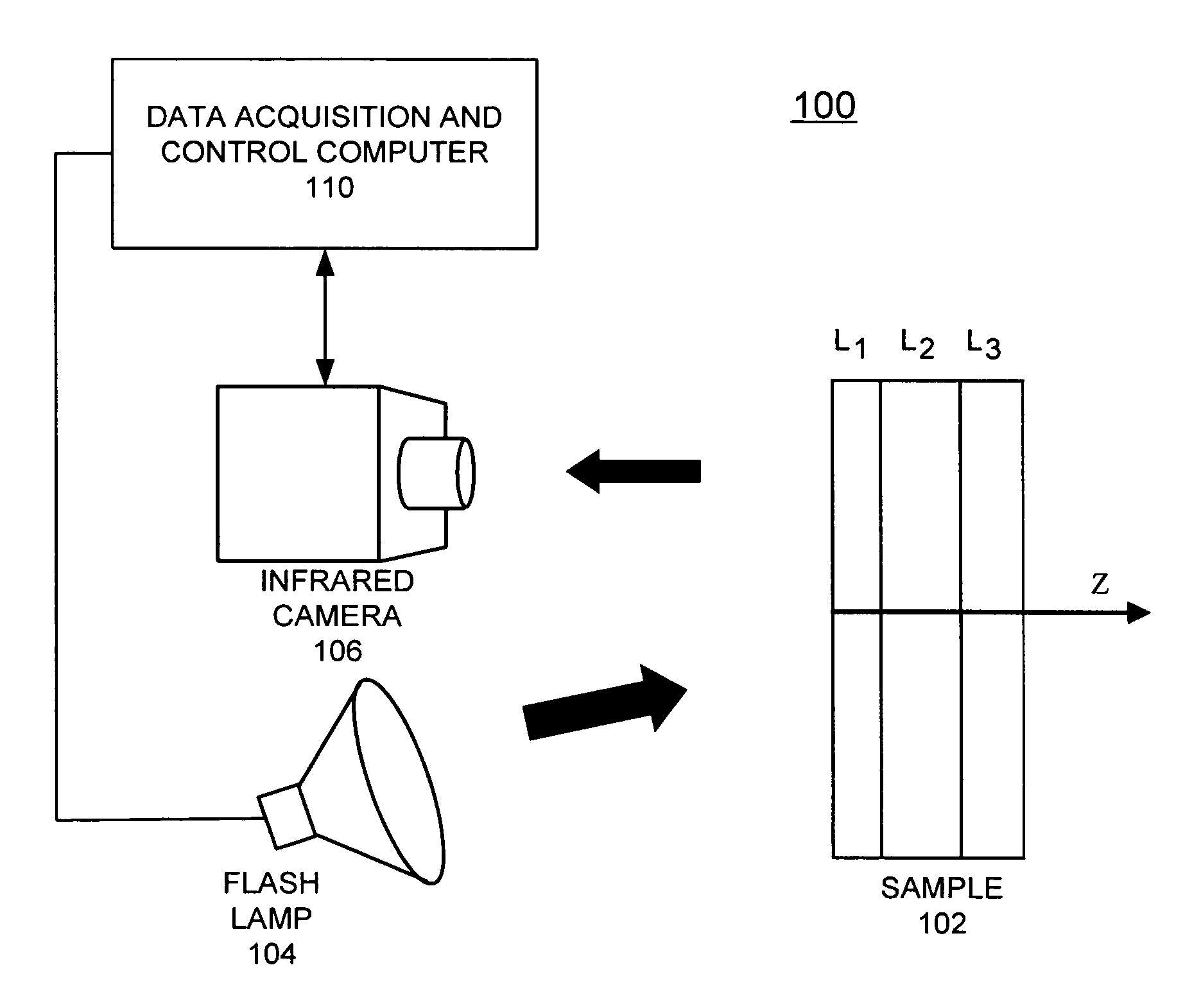
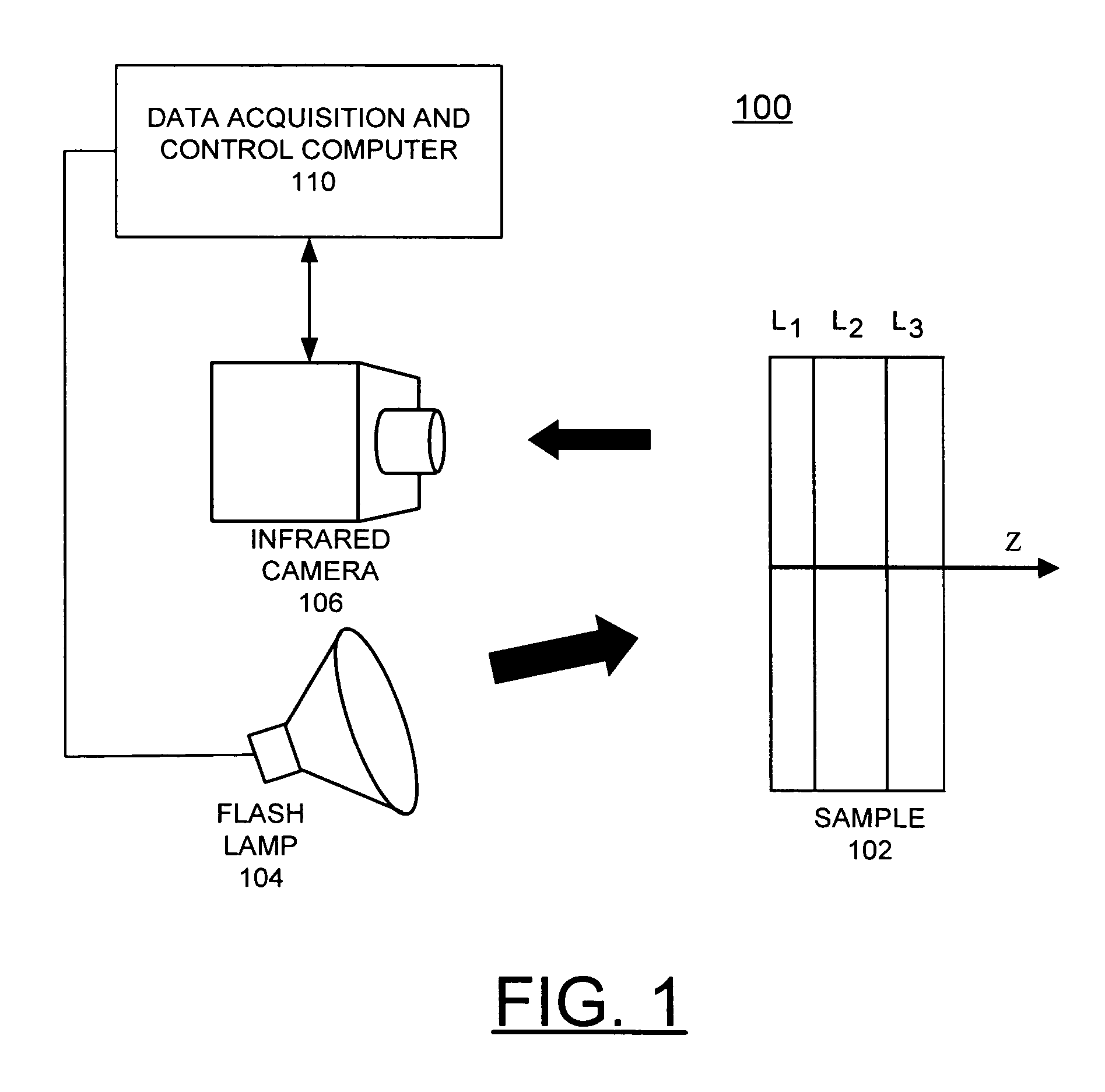
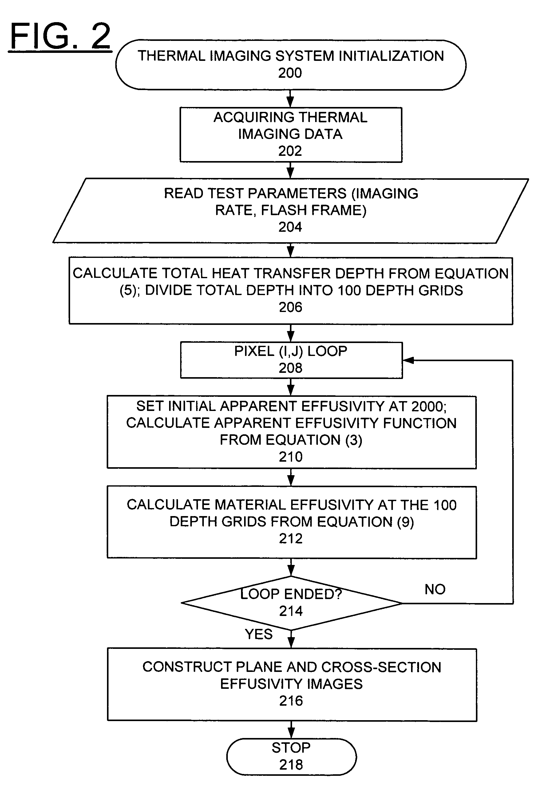
[0028]In accordance with features of the invention, a thermal tomography method converts the temporal series of 2D surface temperature data into a spatial 3D distribution of material effusivity under the surface.

[0029]In comparison, conventional thermal imaging methods only process the surface temperature in temporal domain to determine one or a few parameters at each surface position (a pixel in a 2D image) based on a model of the material system; these methods are considered 2D methods because they cannot provide the distribution of material property under the surface. For example, several methods were developed to detect crack, or delaminations, depth under the surface and the predicted depths at all surface positions are usually presented as a 2D depth map for the surface. Recently, a method for multi-layer materials was developed by the present inventor to determine multiple material parameters including conductivity, optical transmission, and thickness and / or crack depth for e...


PUM


Abstract

A computer-implemented method for automated thermal computed tomography includes providing an input of heat, for example, with a flash lamp, onto the surface of a sample. The amount of heat and the temperature rise necessary are dependent on the thermal conductivity and the thickness of the sample being inspected. An infrared camera takes a rapid series of thermal images of the surface of the article, at a selected rate, which can vary from 100 to 2000 frames per second. Each infrared frame tracks the thermal energy as it passes from the surface through the material. Once the infrared data is collected, a data acquisition and control computer processes the collected infrared data to form a three-dimensional (3D) thermal effusivity image.

Description

[0001]The United States Government has rights in this invention pursuant to Contract No. W-31-109-ENG-38 between the United States Government and Argonne National Laboratory.FIELD OF THE INVENTION[0002]The present invention relates to an improved method for analyzing materials, which may be multilayer and inhomogeneous, from one-sided pulsed thermal imaging. More specifically this invention relates to a method for thermal computed tomography from one-sided pulsed thermal imaging. Still more specifically this invention relates to a method and computer program product for automated 3D imaging of subsurface material properties by one-sided pulsed thermal imaging.DESCRIPTION OF THE RELATED ART[0003]Pulsed thermal imaging is widely used for nondestructive evaluation (NDE) of advanced materials and components. The premise is that internal flaws, such as, disbonds, voids or inclusions, affect the flow of heat from the surface of a solid.[0004]For example, U.S. Pat. No. 6,517,236 issued Feb...

Claims


Application Information

Patent Timeline
IPC IPC(8): G01J5/58
CPCA61B5/015G01J5/0003G01N25/72G01J2005/0077
Inventor SUN, JIANGANG
Owner UCHICAGO ARGONNE LLC
Why Eureka
Try Eureka