Moving object detection using low illumination depth capable computer vision

a computer vision and moving object technology, applied in scene recognition, instruments, computing, etc., can solve the problems of computationally expensive ego-motion calculations, use in real-time vision systems, and explicit us

Active Publication Date: 2008-04-29
HONDA MOTOR CO LTD
View PDF29 Cites 63 Cited by
  • Summary
  • Abstract
  • Description
  • Claims
  • Application Information

AI Technical Summary

Problems solved by technology

However, one drawback of these approaches for use in real-time vision systems is that they often involve explicit ego-motion computation or a motion / flow constraint.
Ego-motion calculations are computationally expensive and severely impact the performance of real-time vision systems.
However, the filtering process is complicated and subject to failure because in practice it is difficult to enumerate all possible shapes humans can take.

Method used


Image

  • Moving object detection using low illumination depth capable computer vision
  • Moving object detection using low illumination depth capable computer vision
  • Moving object detection using low illumination depth capable computer vision

Examples


Embodiment Construction

[0031]The Figures and the following description relate to preferred embodiments of the present invention by way of illustration only. It should be noted that from the following discussion, alternative embodiments of the structures and methods disclosed herein will be readily recognized as viable alternatives that may be employed without departing from the principles of the claimed invention.

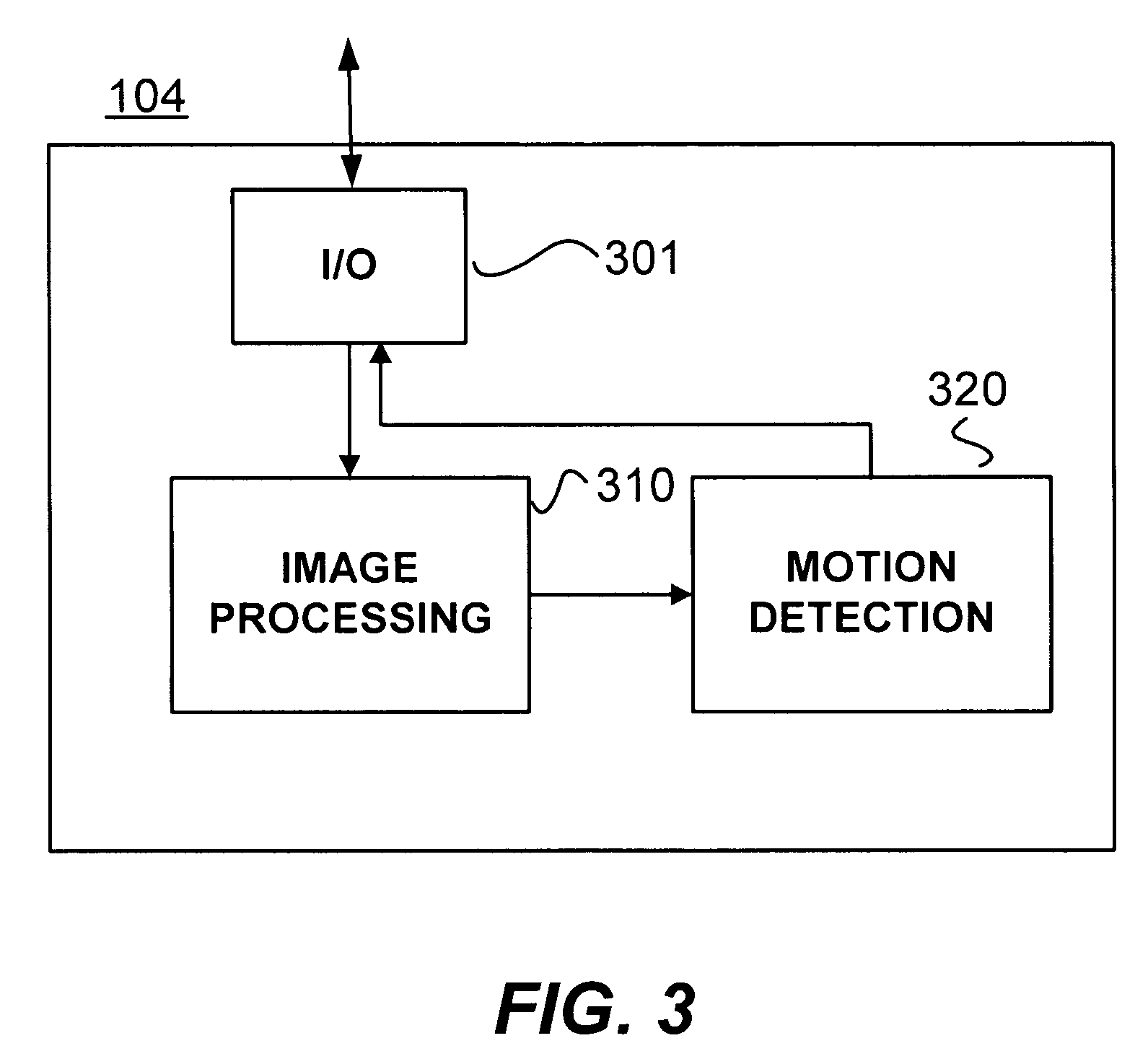
[0032]Referring now to Figure (“FIG.”) 1, one embodiment of a computer vision system 100 on a moving platform 101 is shown. The moving platform 101 moves with respect to a background or frame of reference 103. The computer vision system 100 includes an imaging subsystem 102, a computing subsystem 104, and an output subsystem 106. The imaging subsystem 102 captures the image data for processing by the computing subsystem 104. The computing subsystem 104 is connected to the imaging subsystem 102 to receive the image data as input. The computing subsystem 104 implements image processing algorithms t...


PUM


Abstract

Moving object detection is based on low illumination image data that includes distance or depth information. The vision system operates on a platform with a dominant translational motion and with a small amount of rotational motion. Detection of moving objects whose motions are not consistent with the movement of the background is complementary to shape-based approaches. For low illumination computer-based vision assistance a two-stage technique is used for simultaneous and subsequent frame blob correspondence. Using average scene disparity, motion is detected without explicit ego-motion calculation. These techniques make use of characteristics of infrared sensitive video data, in which heat emitting objects appear as hotspots.

Description

RELATED APPLICATIONS[0001]This application is related to and claims priority from U.S. Provisional Patent Application Ser. No. 60 / 510,179 titled “Pedestrian Detection Using Stereo Night Vision” and filed on Oct. 9, 2003 by the same inventors, which is incorporated herein by reference in its entirety.FIELD OF THE INVENTION[0002]The present invention relates generally to real-time computer vision and more particularly to low illumination computer based recognition of moving objects from a moving platform.BACKGROUND OF THE INVENTION[0003]Computer vision is used to assist or perform humans in performing many functions. Computer vision can be more accurate and better suited than human vision in many applications. For example, computer vision for surveillance applications can better detect moving objects and recognize shapes for indefinite periods of time simply using a set of cameras in conjunction with various computer algorithms (e.g., background subtraction).[0004]Some applications re...

Claims


Application Information

Patent Timeline
Patent Type & Authority Patents(United States)
IPC IPC(8): G06K9/00G06FG06V10/143
CPCG06K9/00369G06K9/00805G06K9/2018G06V40/103G06V20/58G06V10/143
Inventor FUJIMURA, KIKUOLIU, XIA
Owner HONDA MOTOR CO LTD
Why Eureka
Try Eureka