Venting system for use with a foam-in bag dispensing system

a technology of foam-in-bag and venting system, which is applied in the direction of liquid material, packaging goods, transportation and packaging, etc., can solve the problems of poor foam flow within the bag, insufficient vent formation, and shrinkage of foam, so as to reduce the possibility of foam shrinkage, minimize the restriction of foam flow and distribution, and facilitate the effect of implementation

Active Publication Date: 2008-05-06
PREGIS INTELLIPACK CORP
View PDF27 Cites 20 Cited by
  • Summary
  • Abstract
  • Description
  • Claims
  • Application Information

AI Technical Summary

Benefits of technology

[0009]The present invention is directed at providing a venting system that is particularly suited for a foam-in-bag dispensing system which helps avoid or lessen the effect of the numerous drawbacks associated with the prior art systems such as those described above. In so doing, the present invention presents a highly versatile system that provides numerous advantageous features without invoking added complexity and added components, which is a common tendency in the prior art systems, particularly of late.
[0011]The present invention further includes alternate arrangements as in venting devices which utilize an alternate vent formation means as in a heat source (e.g., electric resistance or high energy light, etc), although a blade device is preferred as it avoids added complexity and is low cost and easy to replace. Alternate combinations include, for example, heated blades or a combination of positioning of the venting devices (e.g., replacing different cane locations including venting within an inch or two of opposite edges of the film), although the noted “C-fold” only side positioning provides for vent formation relative to a known condition edge (unlike the alternate side which may have a defect during seal formation). Additional alternate arrangement under the present invention include a combination of blade venting with edge seal interruption (e.g., a blade vent assembly used in conjunction with a system such as the intermittent labyrinth side seam in U.S. Pat. No. 4,999,975 or one of the other interrupted side seam vent arrangements described above) or in conjunction with a small hole (e.g., spike formed vented film sheet as seen in U.S. Pat. No. 5,794,406). Again, however for the avoidance of complexity and added repair and film feed disruption potential the vent systems described in greater detail below as preferred embodiments are preferable for most vent need environments.
[0012]Some of the features of a preferred embodiment include a blade venting device with a blade mounted inside of its own customized blade housing. A function of the noted blade housing is to provide protection for personnel who handle the blade during installation or service, and the blade housing can be made of metal or plastic. In a dual blade venting system (preferably two separate housings although an integrated system with a single housing and multiple blades is also featured under the present invention) two blade cartridges are mounted in close proximity to the nip zone between two film drive rollers. For example, a preferred system features blade cartridges that are supported by the cane support rod that is located above the nip rollers and runs across the front of many machines in the field (although alternate locations are also featured under the present invention as in roller shaft supported locations such as a similar slide and non-rotation arrangement as featured for the edge sealer in the above noted PCT / US2004 / 014423) with a dual function guide cane / blade housing arrangement, one blade cartridge is located in the cane slot on the right side of the rubber nip roller, while another blade cartridge is located in the cane slot on the left side of the same rubber nip roller (again preferably the one in contact with the C-fold side). In this way, the blade cartridges will perform and anti-wraparound function of the current film canes, upon the canes being replaced by the blade cartridges (in a retrofit situation) or put in what would have been that position in a new machine manufacture.
[0018]To accommodate for different size bags the venting modules are either adjustably supported or positioned at a location which is universal to different sizes as is the adjacent cane embodiment. For example, in one embodiment the mounting base includes a releasable clamp assembly as in an over-center latch preferably with a high friction block for contact with the roller support frame back wall that can be readily repositioned along the frame backwall and clamped back into position (again preferably by at a cane replacement location). Thus, with the preferred embodiment of the invention there is an improved venting which reduces the possibility of foam shrinkage and minimize restrictions to foam flow and distribution within the bag. Also the described double blade venting system is easily retrofittable onto any existing foam-in-bag in the field. Also, the control system to operate the venting knives is relatively easy to implement requiring for most preferred usages simply on / off control of solenoid actuators. Accordingly, there can be avoided relatively complex control system, such as those required to “feather” the flow of electrical current through an electrical cut wire. In addition, partially with a pivot out mount base driver support and releasable cartridge (e.g., a spring or friction lever latch with capture recess assembly as in common with many printer cartridges) the blade holding cartridges will be easy to replace should their blades get dull or damaged. Also, the venting blades are not exposed for undesirable contact to personnel, and are safe to handle during installation and shipping.

Problems solved by technology

Some difficulties experienced with the prior art venting designs include inadequate vent formation and the potential for foam shrinkage and poor in-bag foam flow within the bag due to inadequate venting or over extended vent formation and the associated leakage potential (e.g., a failure to properly control the required temperature differential to differentiate between a seal and vent region during interruption of an edge seal for venting purposes causing either too small or too large a seal interruption).
The interruption technique (such as the feathering of the flow of electrical current to a sealing heat wire or the movement of heat sealing equipment into and out of position) also can introduce undesirable added complexities associated with temperature or equipment controlling particularly in an environment where devices can become coated with foam, worn out or moved in position during use (e.g., melting into a support component).
An additional problem with some prior art is that cut venting is often done on only the front or the back sheet which limits the venting capability.
There is also associated with prior art devices difficulty in repair and replacement for a defective venting component due to for example, difficulty in accessing or difficulty in removing and proper replacement.

Method used


Image

  • Venting system for use with a foam-in bag dispensing system
  • Venting system for use with a foam-in bag dispensing system
  • Venting system for use with a foam-in bag dispensing system

Examples


Embodiment Construction

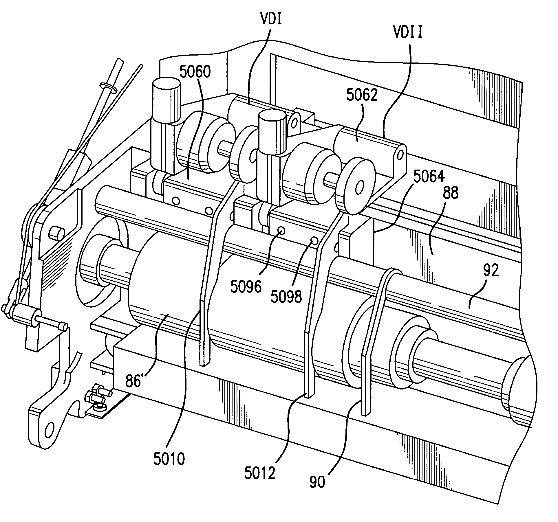
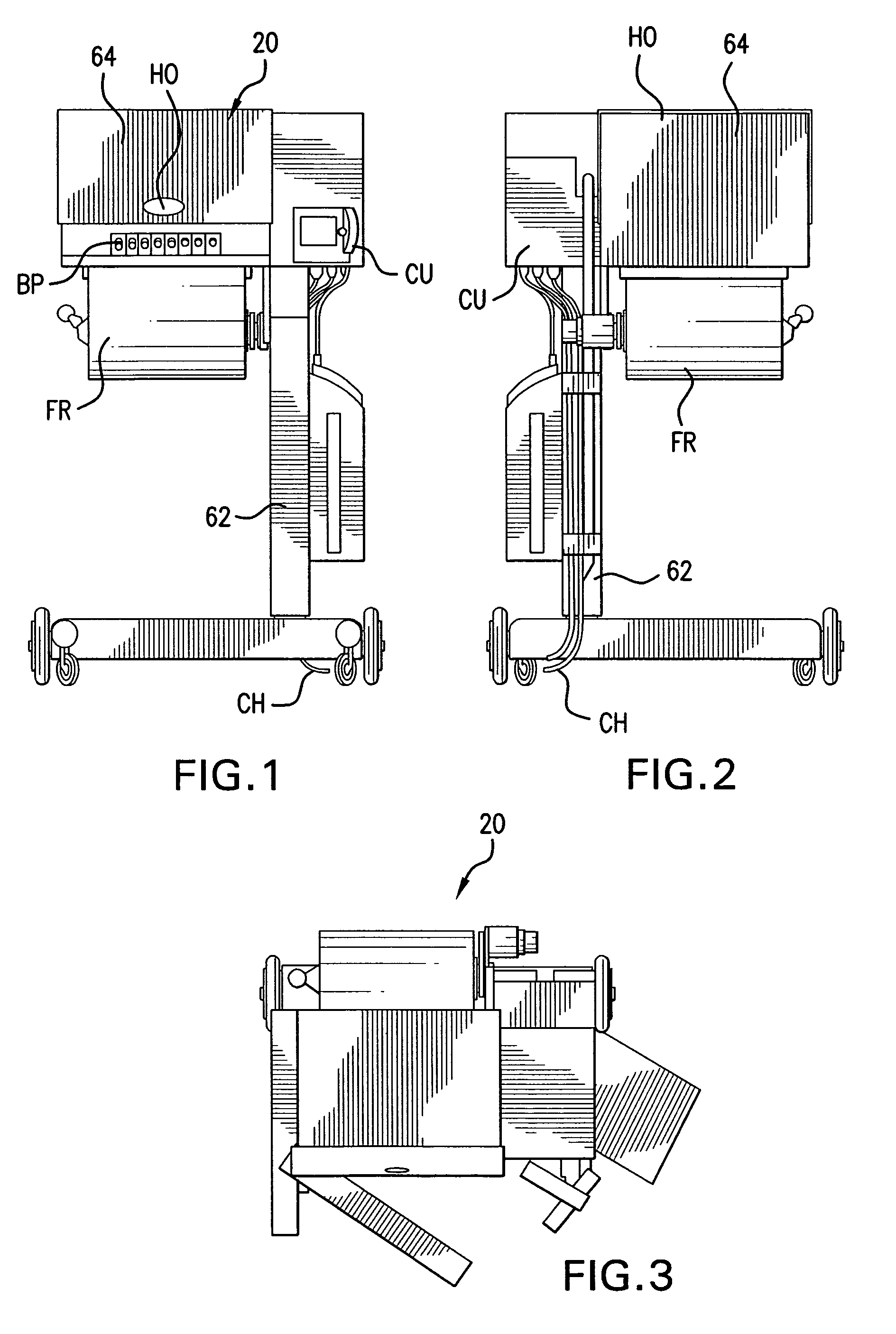
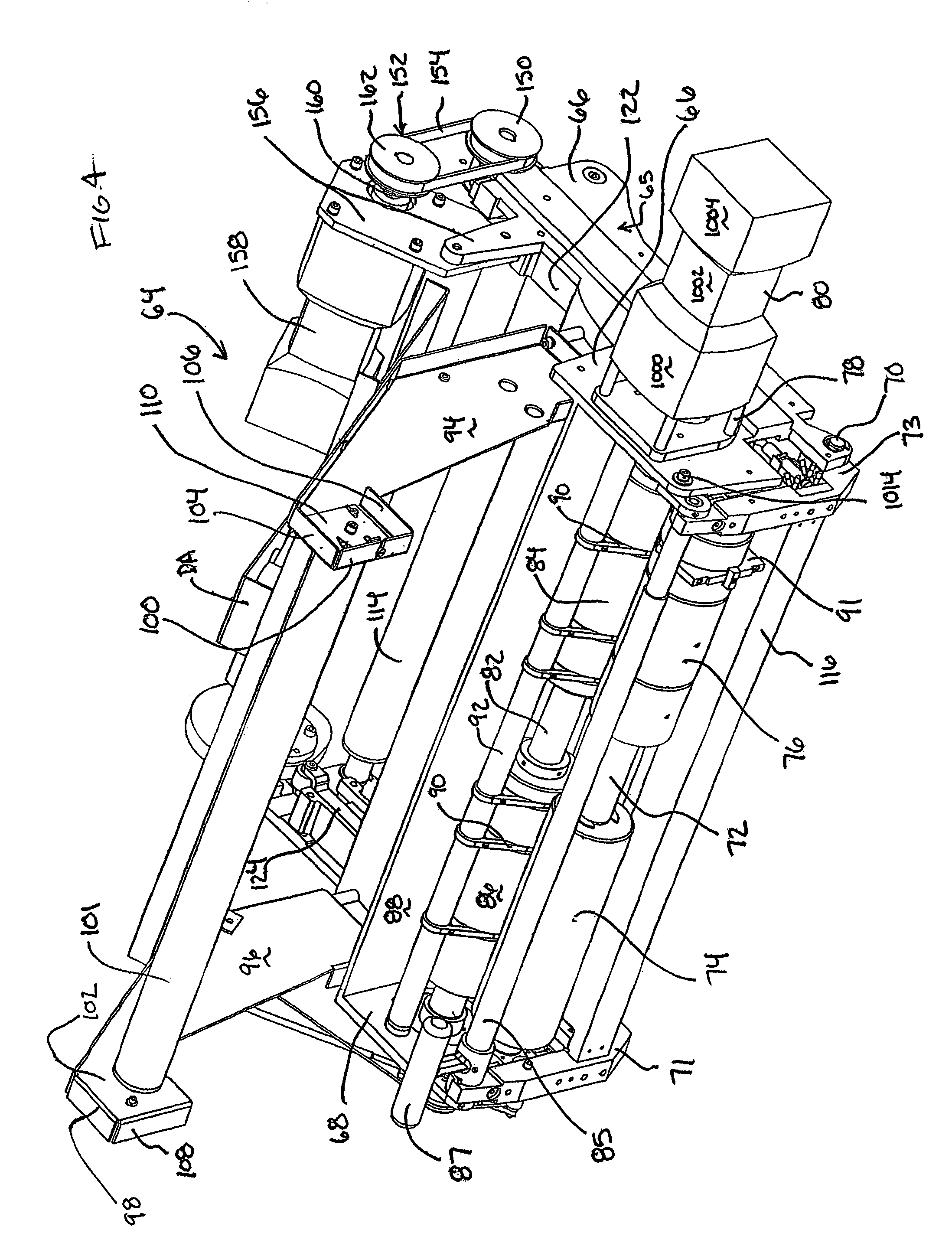
[0045]The venting system of the present invention can be utilized in a variety of bag formation with vent requirement systems such as the foam-in-bag venting system of the above noted PCT Patent Application PCT / US2004 / 014423 (e.g., as part of a retrofit process or in conjunction with an initial manufacture of a foam-in-bag system). FIGS. 1 to 3 illustrate the foam-in-bag dispensing system 20 described in PCT / US2004 / 014423 which represents one of many possible foam-in-bag systems suitable for use with the venting system of the present invention to provide an improved foam-in-bag system. As shown in FIGS. 1-3 the foam-in-bag dispensing system 20 is in communication with a chemical supply (not shown) which typically involves a first chemical supply line from a container source (supplying chemical component A) and a second chemical supply line from a container source (supplying chemical component B) via respective heated chemical hoses CH which feed into a manifold port 198 of the dispe...


PUM

PropertyMeasurementUnit
angleaaaaaaaaaa
widthaaaaaaaaaa
widthaaaaaaaaaa

Abstract

A venting device with base and an adjuster supported by the base, and a driver driving the adjuster. The adjuster includes a film vent former moved by the driver between vent formation mode and non-vent formation mode. The adjuster includes an adjustable blade moving from non-vent mode position with the blade on a first side of the film to vent mode position with a segment of the blade positioned on an opposite film side. The blade has a blade segment traveling within a nip region of the film driver of a foam-in-bag dispenser, where the venting device is nestled in a film drive component slot in the nip zone, and an opposite nip zone roller across the film path has a reception groove receiving the blade segment. The blade is contained in a housing shaped to perform a film wrap around prevention function relative to the bag forming assembly.

Description

CROSS REFERENCE TO RELATED APPLICATION(S)[0001]Priority under 35 U.S.C. § 119(e) is claimed relative to Provisional Patent Application No. 60 / 644,523, filed Jan. 19, 2005, which is incorporated herein by reference.FIELD OF THE INVENTION[0002]The present invention is directed at a venting system for use with a foam-in-bag system such as one which forms a bag from a film feed source and, at the time of bag formation, receives from a dispenser a shot of foam precursor chemical mix. The foam precursor chemical mix expands and releases a gas within the bag formed or being formed with the venting system providing a gas release means in the bag.BACKGROUND OF THE INVENTION[0003]Over the years a variety of material dispensers have been developed including those directed at dispensing foamable material such as polyurethane foam which involves mixing certain chemicals together to form a polymeric product while at the same time generating gases such as carbon dioxide and water vapor. If those c...

Claims


Application Information

Patent Timeline
Patent Type & Authority Patents(United States)
IPC IPC(8): B65B9/06
CPCB29C44/182B29C44/588
Inventor BERTRAM, GEORGEWALKER, DOUG
Owner PREGIS INTELLIPACK CORP
Why Eureka
Try Eureka