A particular problem associated with certain foams is that, once mixed, the organic resin and polyisocyanate generally react relatively rapidly so that their foam product tends to accumulate in all openings through which the material passes.
As a result, the foamable composition, which is often dispensed as a somewhat
viscous liquid, tends to adhere to objects that it strikes and then harden in place.
Many of these
adhesive foamable compositions tenaciously stick to the contact surface making removal particularly difficult.
Solvents are often utilized in an effort to remove the hardened foamable composition from surfaces not intended for contact, but even with solvents (particularly when considering the limitations on the type of solvents suited for worker contact or
exposure) this can prove to be a difficult task.
For example, a “foam-up” in a foam-in-bag dispenser, where the mixed material is not properly confined within a receiving bag, can lead to foam hardening in every nook and cranny of the dispensing system making complete removal not reasonably attainable, particularly when considering the configuration of the prior art systems.
This cold flow
distortion of the Teflon is both beneficial (e.g., allowing for the conformance of material about surfaces intended to be sealed off) and a cause of several problems, including the potential for the loss of the fit between the bore and the valving rod as well as the fit between the openings (e.g., ports) through which the separate precursors enter the bore for mixing and then dispensing.
Under these prior art systems, however, over time the sealing quality of the core is lost at least to some extent allowing for an initial build up of the hardenable material which can lead to a cycle of seal degradation and worsening build up of hardened material.
This in turn can lead to a variety of problems including the partial blockage of chemical inlet ports so as to alter the desired flow mix and degrade the quality of foam produced.
Such buildups cause spraying in the output
stream, and dispensing of the mixture in an improper ratio.
The build up of hardened material can also lead to partial blockage of the dispenser's exit outlet causing a misaiming of the dispensed flow into contact with an undesirable surface (e.g., the operator or various nooks and crannies in the dispenser).
Another source of improper foam output is found in a partially or completely blocked off dispenser outlet tip that, if occurs, can lead the foam spray in undesirable areas or system shutdown if the outlet becomes so blocked as to preclude output.
However, over time these tips tend to load up with hardened foam and eventually become ineffective.
The build of hardened /
adhesive material over time can lead to additional problems such as the valve rod and even a purge only rod, becoming so adhered within
its region of reciprocal travel that either the driver mechanism is unable to move the rod (leading to an oft seen
shut down signal generation in many common prior art systems) or a component along the drive
train breaks off which is often the annular recessed valve rod engagement location relative to some prior art designs.
Thus, even with a brand new dispenser, there are additional requirements involved in attempting to achieve a desired foam product.
The tachometers used in the prior art are relatively sensitive equipment and prone to breakdowns.
These chemical conduit heater wires suffer from a variety of drawbacks such as (a) poor sensor (e.g., thermistors) responsiveness due to non head-on flow positioning of the sensor or difficulty in manipulating the sensor without breakage to be in the proper orientation, (b) difficulty in positioning the tip of the heater wire close enough to the dispenser to avoid cold shot formation and associated material stretch limitations in the heater wire conduit needed to avoid stretching and separation of the dispenser from the tip of the heater wire when the other “fixed” end originates from the pump control region, (c) increased pump weight and an increase in the length and cost associated with the leads extending from the heater wire tip to heater wire control and power source locations at the pump end, (d) an associated increase in
electromagnetic interference (EMI) due to the longer “umbilical” cords and thermister leads, (e) poor thermister reliability in its heavy flex location within the interior of the heater wire, (f) difficulty in feeding heater elements within the outer protective chemical conduit, and (g) cost and production limitations in the overall heater wire and conduit length requiring relatively close positioning of the chemical driver source to the dispenser location.
In addition to the common occurrence of foam dispenser system lock up, cleaning
downtime requirements, poor mix performance in prior art foam-in-bag systems, a dispenser system, featuring an apparatus for automatically fabricating foam filled bags, introduces some added complexity and operator problems.
For example, an automated foam-in-bag system adds additional complexity relative to film supply, film tracking and tensioning, bag sealing /
cutting, bag venting, film feed blockage.
Thus, in addition to the variety of problems associated with the prior art attempts to provide chemicals to the dispenser in the proper rate, keeping the dispenser
cartridge operational, and feeding film properly, the prior art foam-in-bag systems also represent a particular source of additional problems for the operators.
These additional problems include, for example, attempting to understand and operate a highly complicated, multi-component assembly for feeding, sealing, tracking and / or supplying film to the bag formation area; high breakdown or misadjustment occurrence due to the number of components and complex arrangement of the components; high service requirements (also due in part to the number of components and
high complexity of the arrangement in the components);
poor quality bag formation, often associated with poor film tracking performance, difficulty in achieving proper bag seals and cuts, particularly when taking into consideration the degrading and
contamination of heater wires due to, for example, foam build up and the inability to accurately monitor current heated wire temperature application, difficulty in formation and maintaining clear bag vent holes, as well as the inevitable foam
contamination derivable from a number of sources such as the dispenser and / or bag leakage, and
clean up requirements in general and when foam
spillage occurs.
Another particularly problematic area associated with the prior art foam-in-bag system lies in the area of heated
resistance wire replacement, both in regard to edge sealing and in regard to the cross-
cutting sealing systems.
In the prior art systems, there is often required delicate operator manipulation (see for example U.S. Pat. No. 5,376,219) with certain tools to achieve removal and reinsertion of broken, or worn, heated wires (which is a common occurrence in the thin heated resistance wires used in the industry to form the seals and cuts).
In addition, prior art systems suffer from other drawbacks, such as relatively slow bag formation and a slow
throughput of completed bags which, in some systems, is partially due to a reverse feed requirement to break an upper, not-yet-completely formed bag from a completed bag adhered together by a bond formed by the earlier melted and presently cooled plastic material on the heated cross-
cut wire.
The prior art mixing
cartridge driver mechanisms for reciprocating valve rods has also shown in the field to be inadequate as they are subject to often breakdowns and often quickly become unable to achieve rod reciprocation after a minor build up of foam in the
cartridge.
An additional problem associated with the
mixing chamber used on fixed dispenser embodiments such as a foam-in-bag dispenser is the difficulty in proper removal and mounting of a mixing module in the support housing.
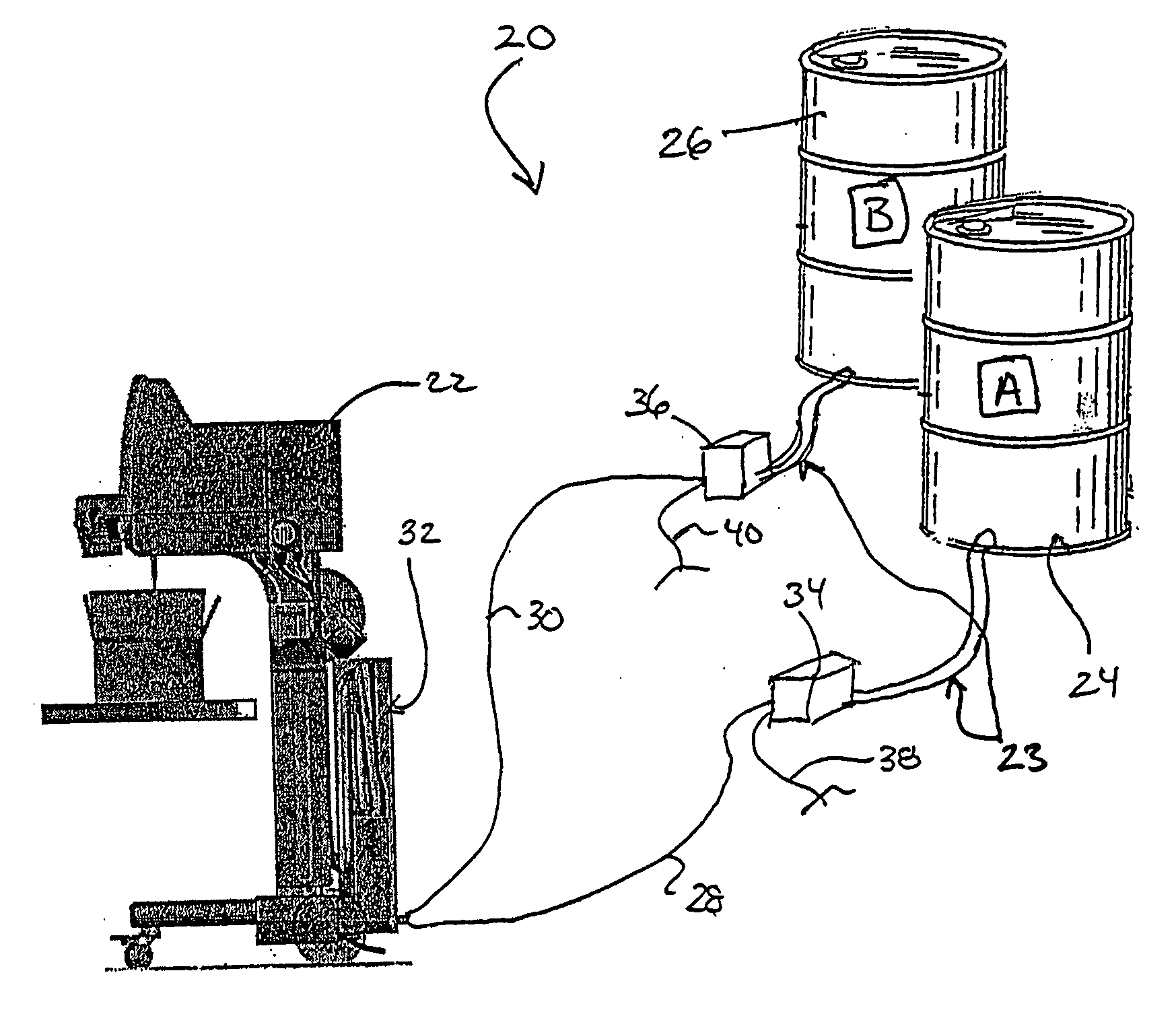
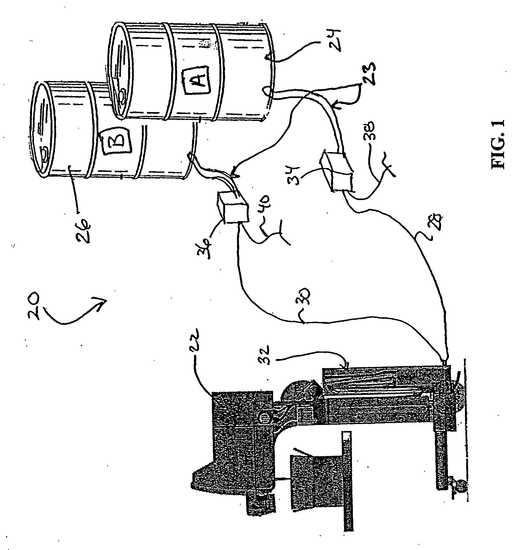
Prior art systems also suffer from hose and
cable management (e.g.,
electronics, chemical supply and
solvent supply) difficulties due to their becoming tangled and in a state of disarray so as to present obstacles to operators and potential equipment malfunctions due to cable or hose interference with moving components or the hoses / cables becoming disconnected and / or damaged.
The pump equipment of prior art systems are also prone to malfunction including the degrading of seals (e.g.,
isocyanate forms hardened crystals when exposed to air which can quickly degrade soft seals).
The pumping systems currently used in the field are also subject to relatively rapid deterioration as they often operate at high rates during usage due to, for example, general inefficiency in driving the chemical from its source to the dispenser outlet.
The common usage of in-
barrel pump systems also introduces limitations in chemical source locations (e.g., typically a 20 foot range limitation for standard heater wire conduit and in
barrel pump systems), which can make for difficulties in some operator facilities where it is required or preferred to have the chemical source located at a greater distance from the dispenser.
The common usage of in-
barrel pumps for prior-art dispenser systems also presents a requirement for multiple chemical sources to achieve the required one-to-one chemical source and pump combination, which in particularly problematic for operators running numerous dispenser systems.
These prior art arrangements present problems from the stand point of the placement of the dispenser and its various components such as filters, chemical valving lines, and other components required for accessing a mixing module, all in the bag formation region.
This positioning places those components in an area highly prone to chemical contact even with a properly functioning dispenser.
Efforts have been made in the prior art to protect the dispenser through the use of covers, but these covers have shown to be highly ineffective in protecting the components.
Once foam hardens on the components they are often made even more difficult to access when servicing is desired.
Also, the non-smooth, multi-protrusion and edge presentment design of prior art foam dispensers, in addition to making cleaning impractical, have a tendency to create film tracking problems and / or require added guidance members to avoid film / dispenser contact.
In addition to the difficulty in achieving proper wire temperature levels in the chemical conduit heater wires, there has also been experienced difficulty in achieving proper end and edge sealing /
cutting, and venting wire temperatures in prior art foam-in-bag systems.
There is also associated with prior art systems problems in achieving proper positioning and in gaining access for servicing heater wires.
The two most common prior art systems take different approaches with a first utilizing a rolling heater wire which presents added complexity in power supply as well as difficulty in removing and re-inserting heater wires.
The second approach uses a non-rolling drag technique (e.g., U.S. Pat. No. 6,472,638) that, while being easy to remove and re-insert, has experienced difficulty in the field in maintaining a proper location of the exposed heater wire relative to the film being driven thereby, which is due in part to a tendency for the heated seal, wires becoming more and more embedded in the underlying support.
Film replenishment in the prior art systems has also proven to be difficult.
Accessing prior art systems to remove the emptied roll and to replace it with a new role, which can be relatively heavy as in 25 lbs. or so, is only achieved with great difficulty due to the
insertion location being in the rear,
intermediate region of a typical foam-in-bag system design.
This location is highly straining on the operator.
Many prior art foam-in-bag systems and other automated dispending systems have shown in the field to have high service requirements due to, for example, breakdowns and rapid supply usage requirements (e.g., film,
solvent, precursor chemicals, etc.).
The prior art systems suffer from the problem of difficult and often non-adequate servicing which can be operator or service representative induced (e.g., failing to monitor own supply levels or anticipating level of usage or difficulty in responding timely to service requests which are often on an emergency or rush basis as any down time can be highly disruptive to an operator in timely meeting orders).
As can be seen there are numerous potential areas that can create problems in the field of dispensing.

