Crankshaft of in-line four-cylinder engine

a four-cylinder engine and crankshaft technology, applied in the direction of shafts, bearings, pumps, etc., can solve the problems of difficult to maintain an oil film between the journal jb>3, uneven crankshaft rotation, vibration, etc., to suppress the increase in the weight of the entire crankshaft and maintain the rigidity against torsional deformation. , the effect of reducing the weight of the cranksha

Inactive Publication Date: 2008-05-06
TOYOTA JIDOSHA KK
View PDF22 Cites 14 Cited by
  • Summary
  • Abstract
  • Description
  • Claims
  • Application Information

AI Technical Summary

Benefits of technology

[0008]Accordingly, it is an objective of the present invention to provide a crankshaft that reliably maintains the rigidity against torsional deformation and the thickness of oil films on journals, while suppressing increase in the weight of the entire crankshaft.

Problems solved by technology

Such eccentric crankpins hinder smooth rotation of the crankshaft and produce vibration.
This makes it difficult to maintain an oil film between the journal J3 and the corresponding bearing.
However, this configuration is unfavorable since the weight of the entire crankshaft would be increased.

Method used


Image

  • Crankshaft of in-line four-cylinder engine
  • Crankshaft of in-line four-cylinder engine
  • Crankshaft of in-line four-cylinder engine

Examples


Embodiment Construction

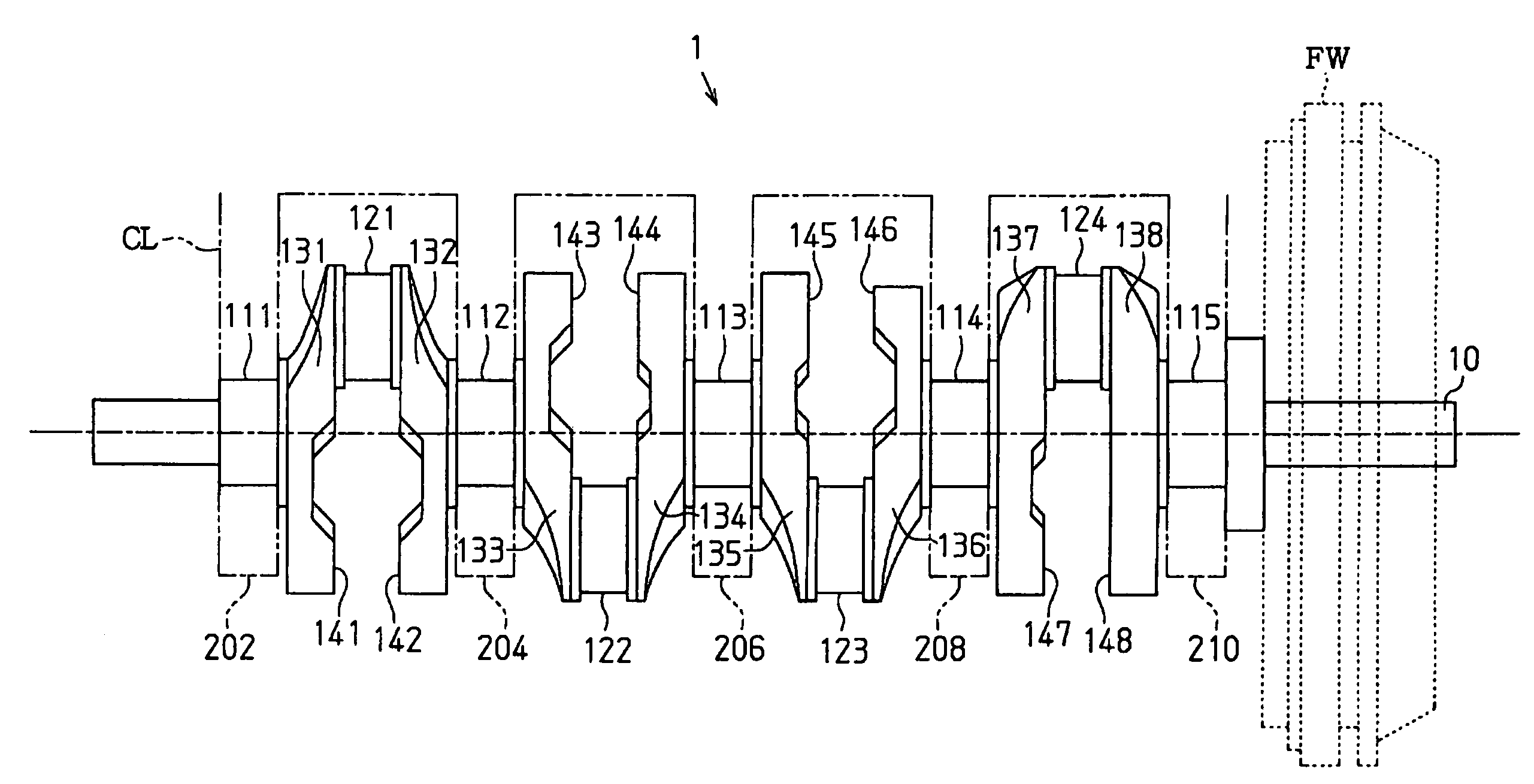
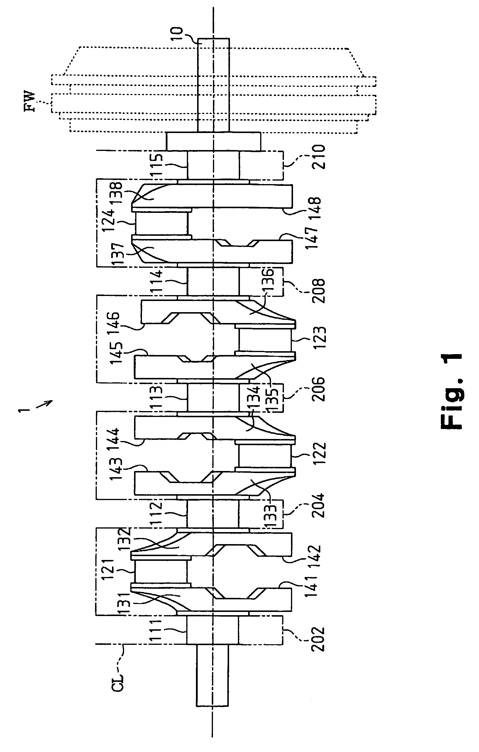
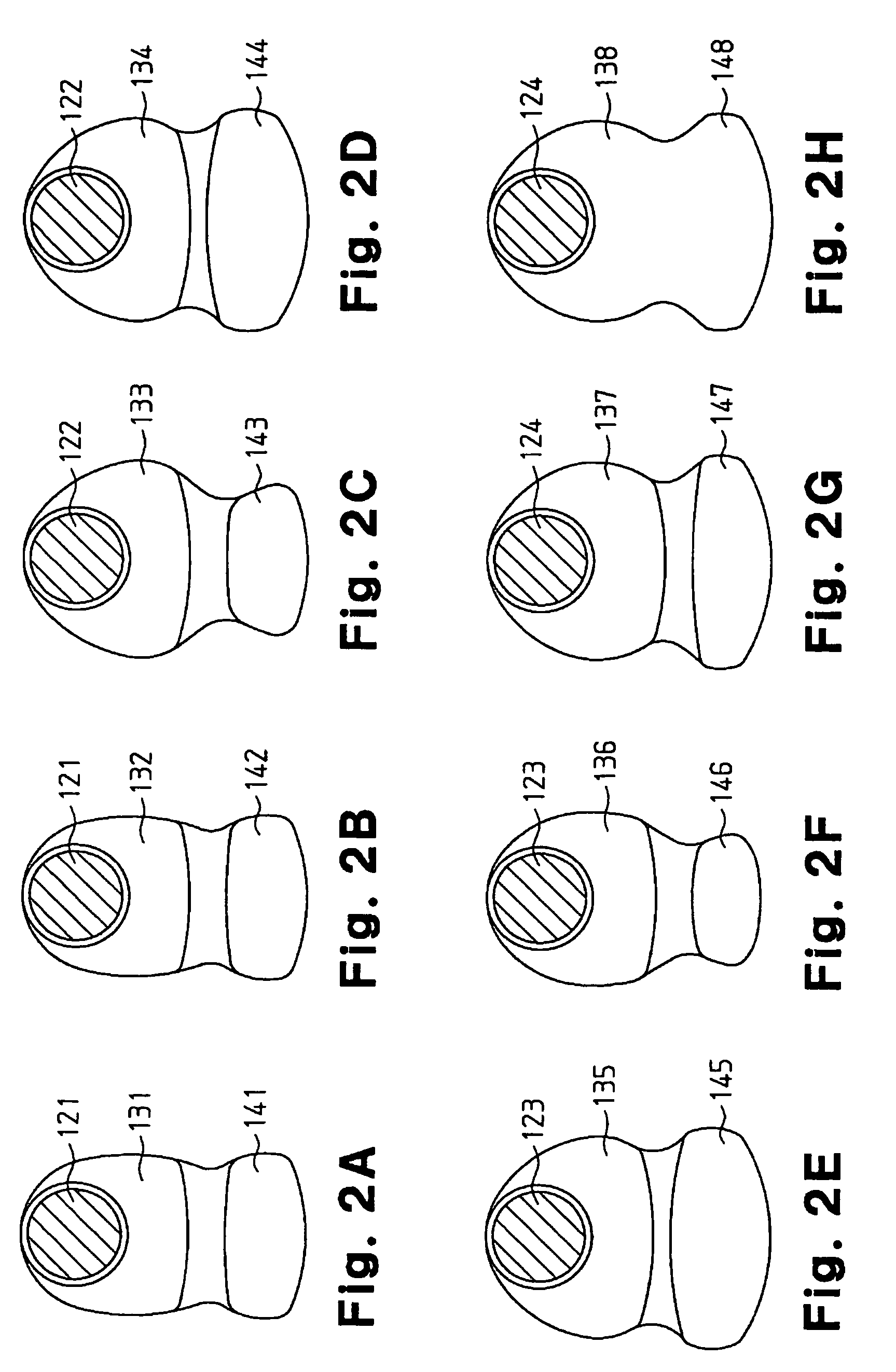
[0017]The present invention will now be described with reference to FIGS. 1 to 2H. FIG. 1 is a front view illustrating a crankshaft 1 of an in-line four-cylinder engine according to one embodiment of the present invention. The crankshaft 1 includes five journals 111 to 115 rotatably supported by bearings 202, 204, 206, and 208 of a cylinder block CL, four crankpins 121 to 124 each corresponding to one of the engine cylinders (not shown), and eight arms 131 to 138 alternately coupling the journals 111 to 115 and the crankpins 121 to 124. The arms 131 to 138 extend in radial directions in relation to the rotation axis of the crankshaft 1, in other words, in relation to the axis of the journals 111 to 115. Each of the crankpins 121 to 124 is coupled to a pair of the arms 131 to 138 sandwiching the crankpin and is located at a position eccentric from the rotation center of the crankshaft 1. The arms 131 to 138 are provided with counterweights 141 to 148 located at ends opposite to the e...


PUM


Abstract

In a crankshaft of an in-line four-cylinder engine, an arm that is closest to a flywheel has a greater average thickness in a direction of the rotation axis of the crankshaft than those of other arms. Two of the arms that are coupled to both sides of the third journal from the flywheel each have a center of gravity closer to its own counterweight compared to the centers of gravity of the arms that face the two arms with corresponding crankpins in between. Accordingly, the rigidity against torsional deformation and the thickness of oil films on the journals are reliably maintained while suppressing increase in the weight of the entire crankshaft.

Description

BACKGROUND OF THE INVENTION[0001]The present invention relates to a crankshaft of an in-line four-cylinder engine.[0002]In an internal combustion engine, a crankshaft and connecting rods convert linear movement of pistons into rotation. The crankshaft rotates at a high speed while receiving great load from the pistons through the connecting rods. Accordingly, the crankshaft is required to have a high rigidity. A crankshaft includes arms extending in radial directions in relation to the axis of a rotary shaft of the crankshaft, and crankpins that are coupled to the arms and eccentric from the rotation axis of the crankshaft. Such eccentric crankpins hinder smooth rotation of the crankshaft and produce vibration. To suppress such vibration, in the configuration disclosed in Japanese Laid-Open Patent Publication No. 5-26297, each arm has a counterweight in a section opposite to the part to which a crankpin is coupled, thereby keeping the balance of the entire crankshaft during rotation...

Claims


Application Information

Patent Timeline
Patent Type & Authority Patents(United States)
IPC IPC(8): F02B75/06F16C11/00
CPCF16C3/06Y10T74/2183Y10T74/2174F16C3/08F16C3/20F16C2360/22
Inventor YAMAMOTO, TAKESHIAOYAMA, TAKAYUKIINAGAKI, MIZUHOMORI, NOBUYUKIYOSHIZAKI, HIROTOSHI
Owner TOYOTA JIDOSHA KK
Why Eureka
Try Eureka