
Apparatus and method for replacing existing actuator zone valves in an HVAC system with a ball valve

a technology of actuator and actuator, which is applied in the direction of valve arrangement, plug valve, mechanical equipment, etc., can solve the problems of spring force, not being able to provide ball valve significantly less than half of its full flow capacity, and being difficult to repla

Active Publication Date: 2008-05-06
SCHNEIDER ELECTRIC BUILDINGS AMERICAS INC
View PDF12 Cites 4 Cited by
  • Summary
  • Abstract
  • Description
  • Claims
  • Application Information

AI Technical Summary

Benefits of technology

"The invention provides an apparatus and method for replacing existing actuator driven zone valves in an HVAC system, particularly valves of the rubber paddle type having actuators providing less than 90 degrees of rotation. The apparatus includes a ball valve with a skewed seat bearing that blocks flow through the flowpath when the valve member is rotated through an angle of substantially less than 90 degrees. The actuator from the existing zone valve can be re-used with the provided ball valve apparatus and method. The technical effect of the invention is to provide a more efficient and cost-effective way to replace these valves in an HVAC system."

Problems solved by technology

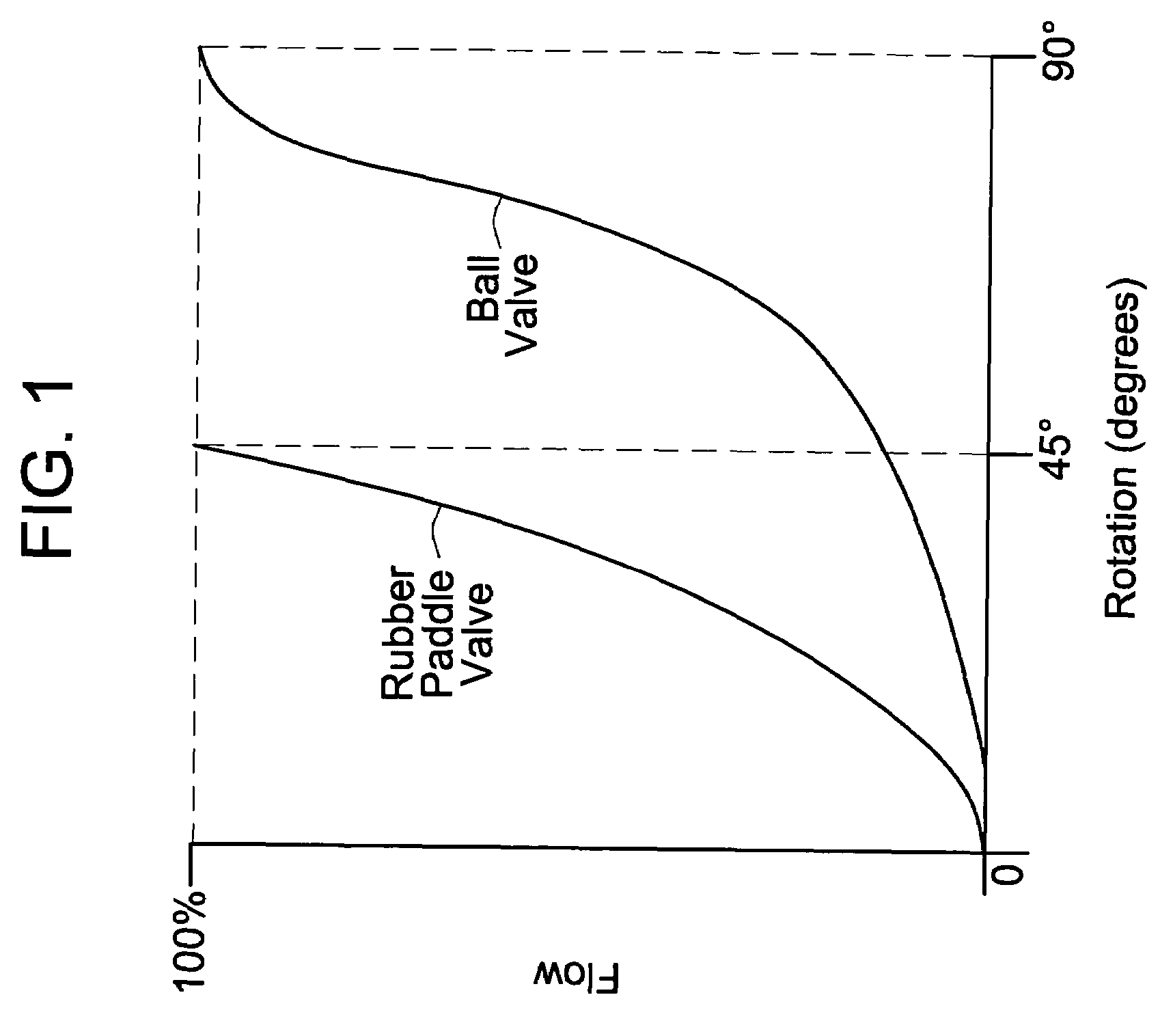
Unfortunately, as illustrated in FIG. 1, the valve element of a ball valve must be rotated through ninety degrees to move from a fully open to a fully closed position.
This results in the ball valve providing significantly less than half of its full flow capacity during the first half of its full 90 degree range of angular rotation, due to the inherent non-linear flow characteristics of the ball valve.
Modifying an existing spring return actuator, designed to provide forty-five degrees or less rotation to a rubber paddle type valve, so that it could provide 90 degrees of rotation and sufficient spring force to drive a ball valve through an angle of rotation of 90 degrees, is typically not possible.
A combination of these factors would require that a spring return actuator capable of driving a ball valve through a full ninety degree angle of rotation would be significantly larger, heavier and more costly than the existing actuators used for driving rubber paddle type valves through an angle of rotation of forty-five degrees or less.

Method used


Image

  • Apparatus and method for replacing existing actuator zone valves in an HVAC system with a ball valve
  • Apparatus and method for replacing existing actuator zone valves in an HVAC system with a ball valve
  • Apparatus and method for replacing existing actuator zone valves in an HVAC system with a ball valve

Examples


Embodiment Construction

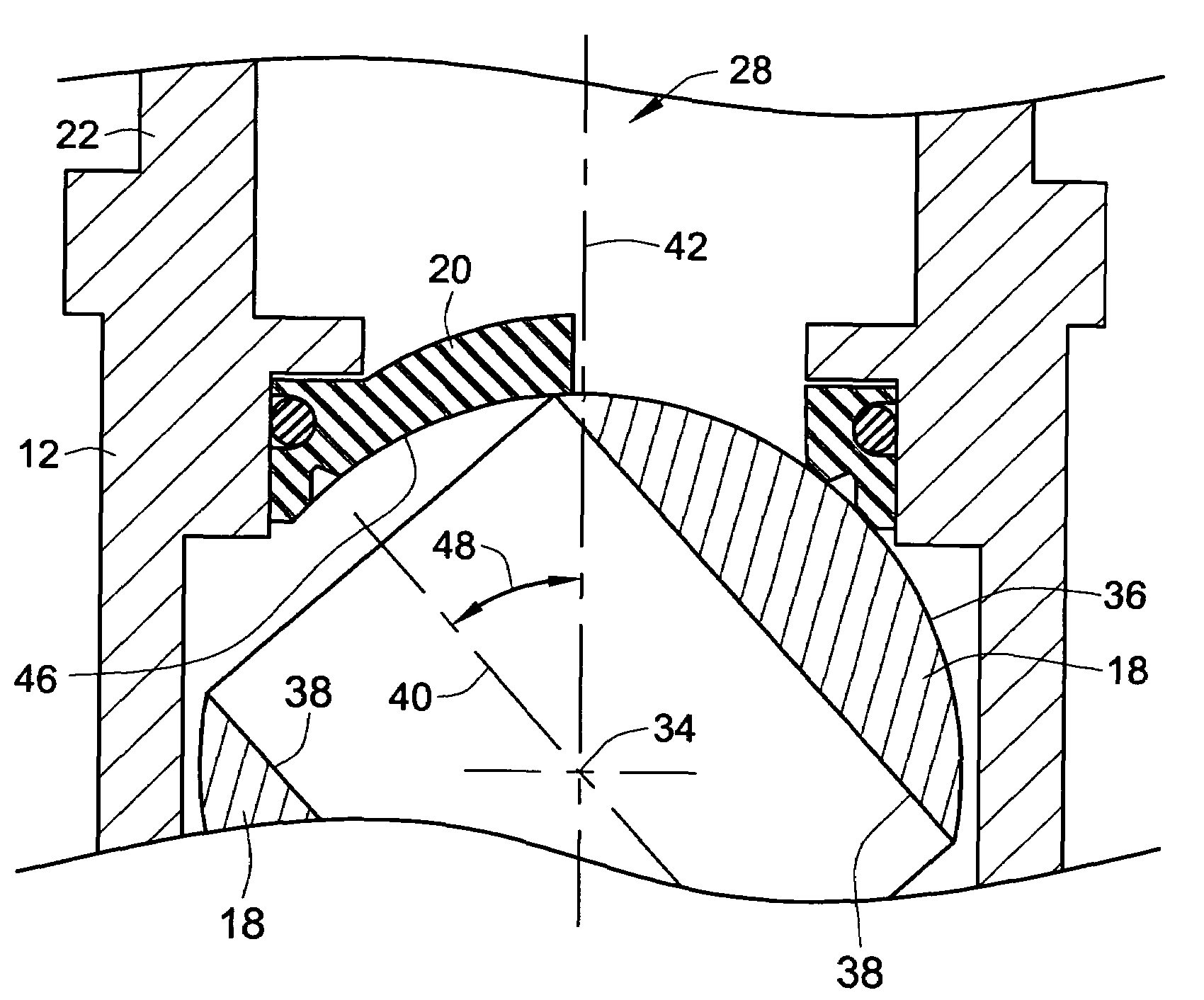
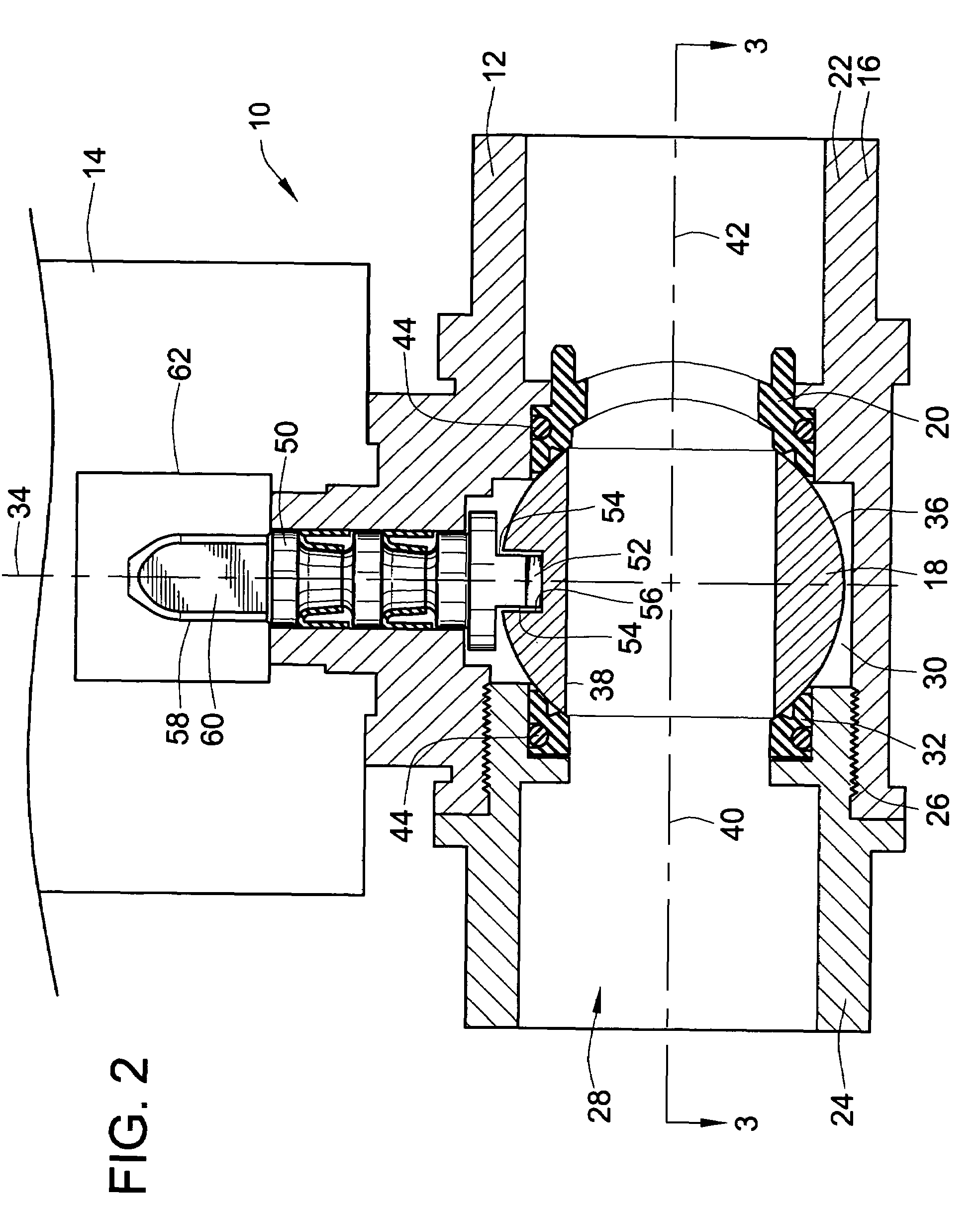
[0032]FIG. 2 shows a first exemplary embodiment of the invention, in the form of a valve apparatus 10 including a ball valve 12 and an actuator 14 operatively attached to the ball valve 12 in the manner described in more detail below. The ball valve 12 includes a valve housing 16, a valve member 18, and a skewed seat bearing 20. The valve housing 16 includes a first section 22 and a second section 24 which are joined by a threaded attachment 26 to define a flow path 28 extending through the housing 16 and a ball receiving cavity 30 within the flow path 28.

[0033]The valve member 18 of the exemplary embodiment is mounted between the skewed seat bearing 20 and a full port inlet bearing 32, within the ball receiving cavity 30, for selective rotation about an axis of rotation 34. The valve member of the exemplary embodiment is a generally spherically shaped ball having a substantially spherical outer surface 36. A through bore 38 extends through the valve member 18 to provide a fully ope...


PUM


Abstract

An apparatus and method are provided for replacing existing actuator driven zone valves in an HVAC system, and particularly valves of the rubber paddle type having actuators providing less than 90 degrees of rotation, with a ball valve including a skewed seat bearing that blocks flow through the flowpath when a valve member of the ball valve is rotated through an angle of substantially less than 90 degrees from a fully open position of the valve at which a bore in the valve member is substantially fully aligned with the flowpath. The actuator from the existing zone valve being replaced may be used with the provided ball valve apparatus and method.

Description

FIELD OF THE INVENTION[0001]This invention relates to ball valves, and more particularly to an apparatus and method for using ball valves to replace existing actuator driven zone valves in an HVAC system, and specifically valves of the rubber paddle type having actuators providing less than 90 degrees of rotation, in such a manner that the actuator from the existing zone valve being replaced may be used with a ball valve according to the invention.BACKGROUND OF THE INVENTION[0002]Hydronic heating ventilating and air conditioning (HVAC) systems for buildings typically include a fluid circuit for delivering heated or chilled water, or other fluids, to occupied spaces in the building. The fluid circuit is typically divided into a number of zones, which can be connected or disconnected from the supply of heated or chilled fluid by zone valves. Such zone valves typically include electric motor driven actuators, which allow the zone valves to be opened or closed from a central location.[0...

Claims


Application Information

Patent Timeline
Patent Type & Authority Patents(United States)
IPC IPC(8): F16K5/06
CPCF16K5/0605F16K5/12
Inventor OH, MICHAEL HUNG-SUN
Owner SCHNEIDER ELECTRIC BUILDINGS AMERICAS INC
Learn More