

Connector for flexible flat strip cables
- Summary
- Abstract
- Description
- Claims
- Application Information
AI Technical Summary
Benefits of technology
Problems solved by technology
Method used
Image

Examples
Embodiment Construction
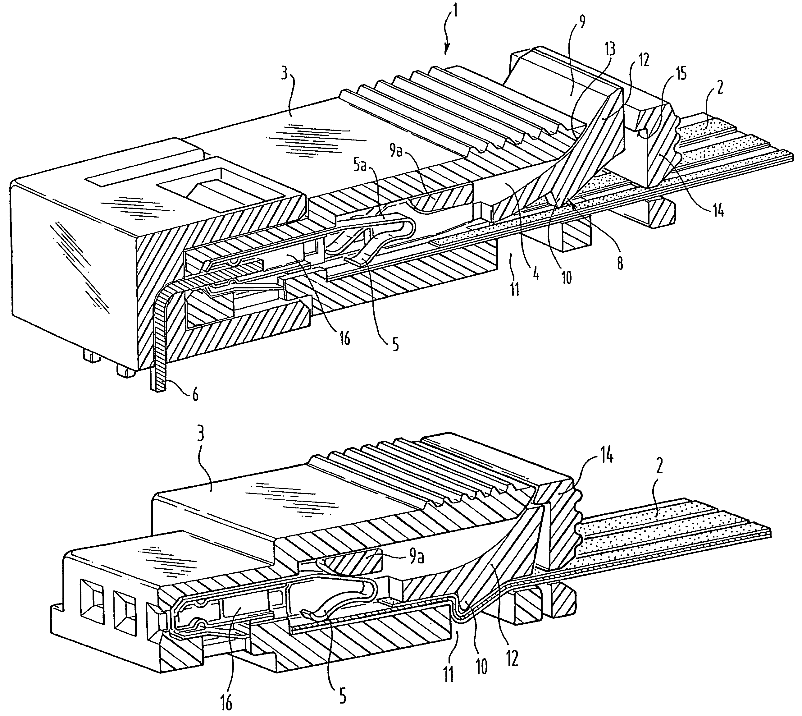
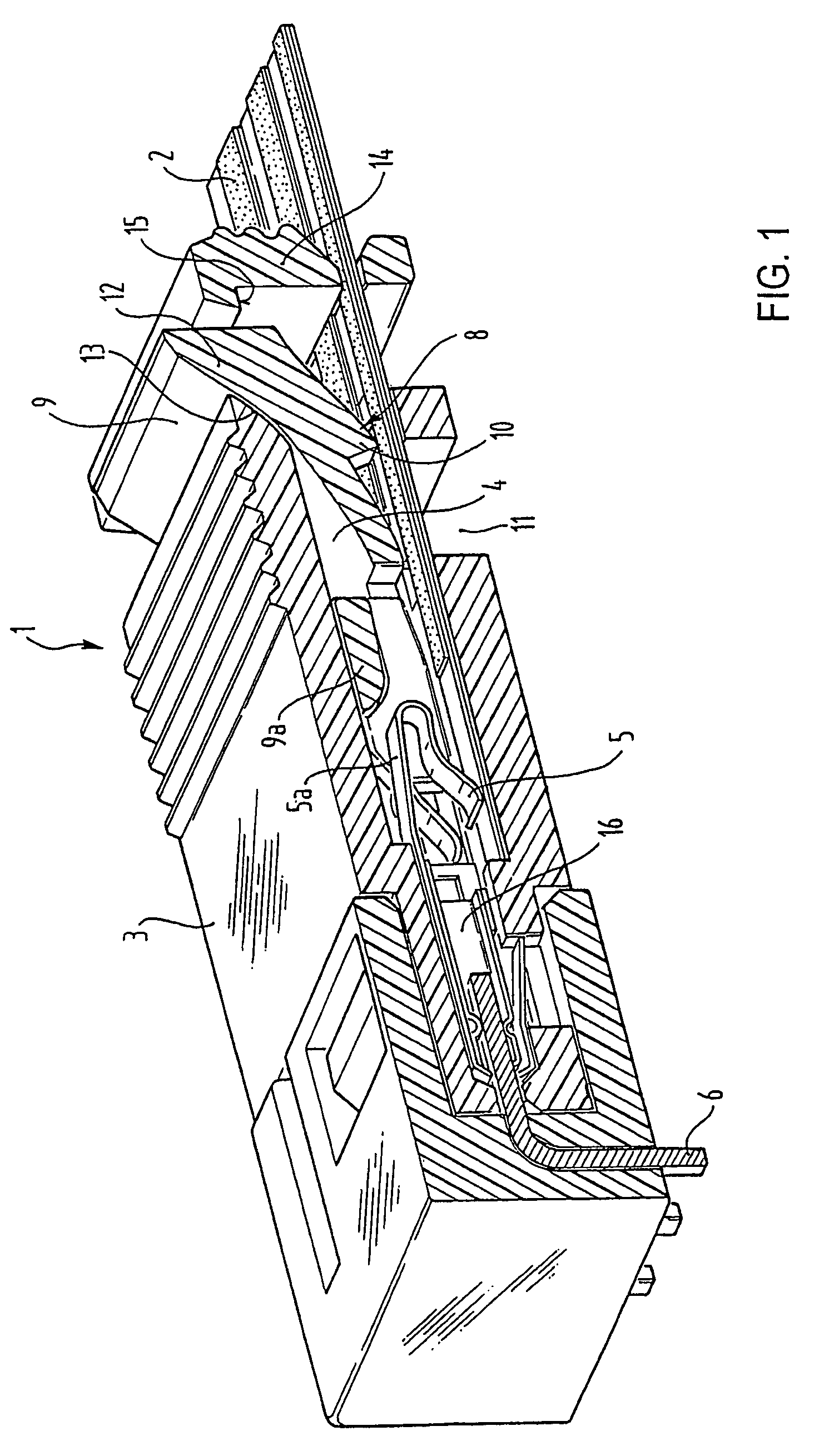
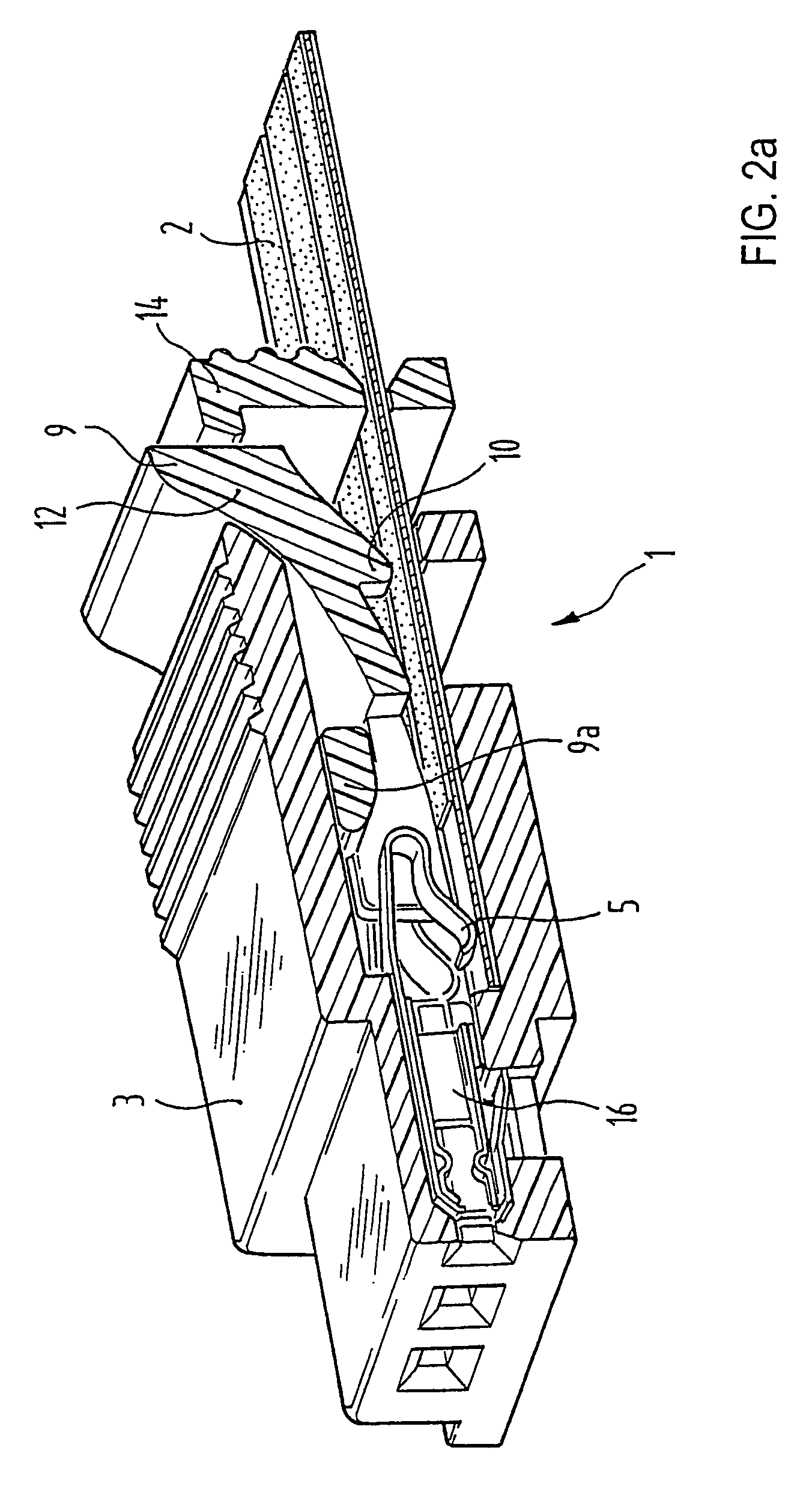
[0011]The connector 1 shown in FIG. 1 has a housing 3, with an introduction opening 4 for a flat flex cable 2. The latter is inserted into the introduction opening 4 until it strikes the end of the opening. At its head end, the flat flex cable 2 has conductive tracks stripped of insulation, onto which press the spring contacts 5. In addition to the flat flex cable 2, a slide 9, which has several functions, is introduced into the introduction opening 4. First of all, it effects a strain relief of the flat flex cable 2, which is described in more detail below, and secondly, it presses the spring contacts 5 more strongly onto the conductive tracks of the flat flex cable 2, which are stripped of insulation. The strain relief is effected by a ramp 12 at the back end of the slide, viewed in the insertion direction, which, with its back end, projects up over the introduction opening 4, when it is in the position prior to assembly. On its bottom side, ramp 12 has a rib 10 running crosswise ...
PUM
 Abstract
Description
Claims
Application Information