Method and apparatus for determining a network topology based on Spanning-tree-Algorithm-designated ports

Active Publication Date: 2008-05-06
CISCO TECH INC
View PDF8 Cites 33 Cited by
  • Summary
  • Abstract
  • Description
  • Claims
  • Application Information

AI Technical Summary

Problems solved by technology

While the data link layer topology of a small LAN with few network bridges and LAN segments may be determined manually with reasonable effort, manually determining the data link layer topology of a large LAN with many network bridges and LAN segments can be extremely difficult.
Over time, the data link layer topology of a LAN can change, due to the addition, removal, reconfiguration, or failure of network devices and network media.
While the CDP-based approach is effective in determining the data link layer topology of a LAN in

Method used


Image

  • Method and apparatus for determining a network topology based on Spanning-tree-Algorithm-designated ports
  • Method and apparatus for determining a network topology based on Spanning-tree-Algorithm-designated ports
  • Method and apparatus for determining a network topology based on Spanning-tree-Algorithm-designated ports

Examples


Embodiment Construction

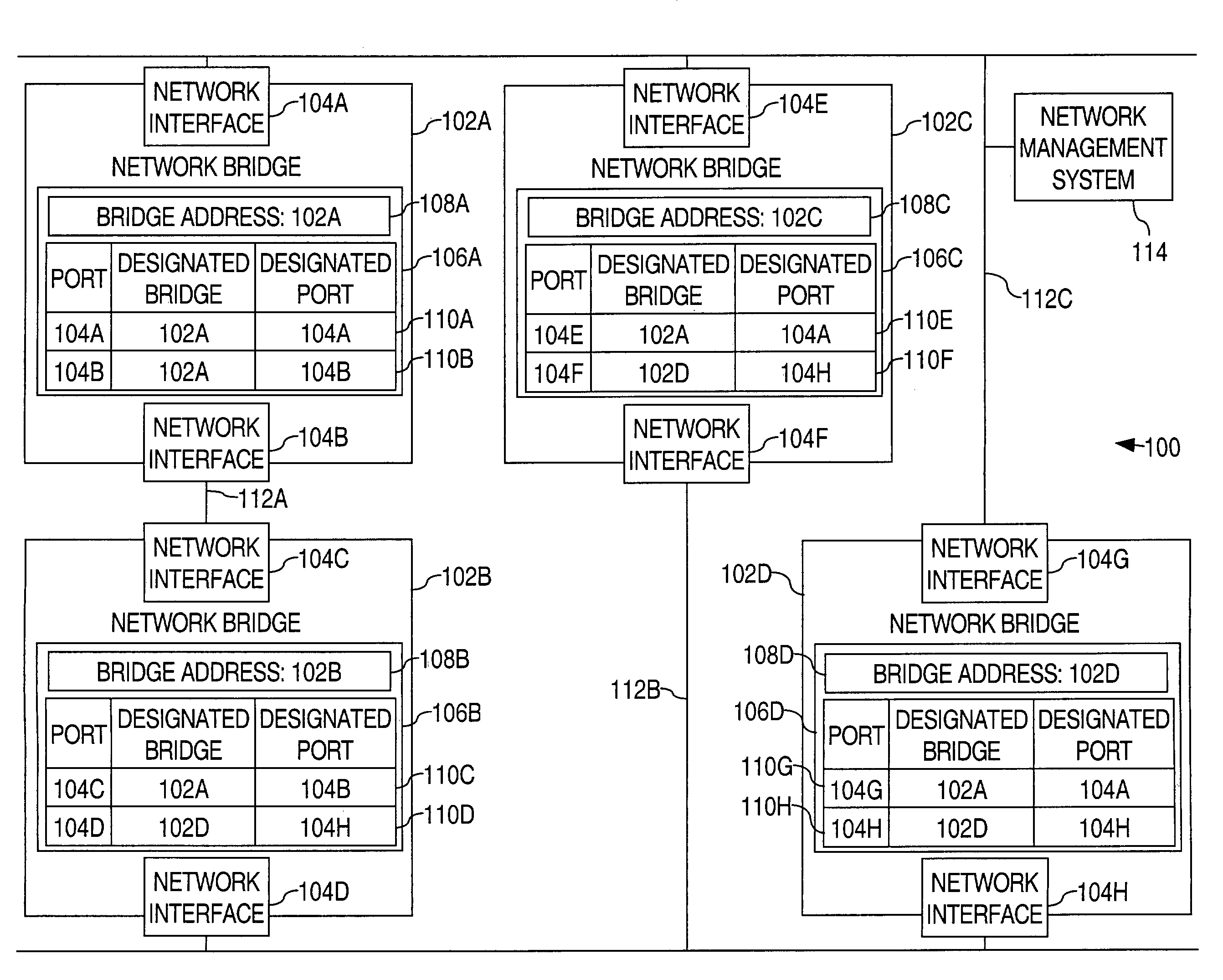
[0023]A method and apparatus for determining a network topology based on Spanning-tree-Algorithm-designated ports is described. In the following description, for the purposes of explanation, numerous specific details are set forth in order to provide a thorough understanding of the present invention. It will be apparent, however, to one skilled in the art that the present invention may be practiced without these specific details. In other instances, well-known structures and devices are shown in block diagram form in order to avoid unnecessarily obscuring the present invention.

[0024]Embodiments are described herein according to the following outline:[0025]1.0 General Overview[0026]2.0 Structural Overview[0027]3.0 Functional Overview[0028]4.0 Method of Determining a Network Topology Based on Spanning-Tree-Algorithm-Designated Ports[0029]5.0 Implementation Mechanisms—Hardware Overview[0030]6.0 Extensions and Alternatives

1.0 General Overview

[0031]The needs identified in the foregoing B...


PUM


Abstract

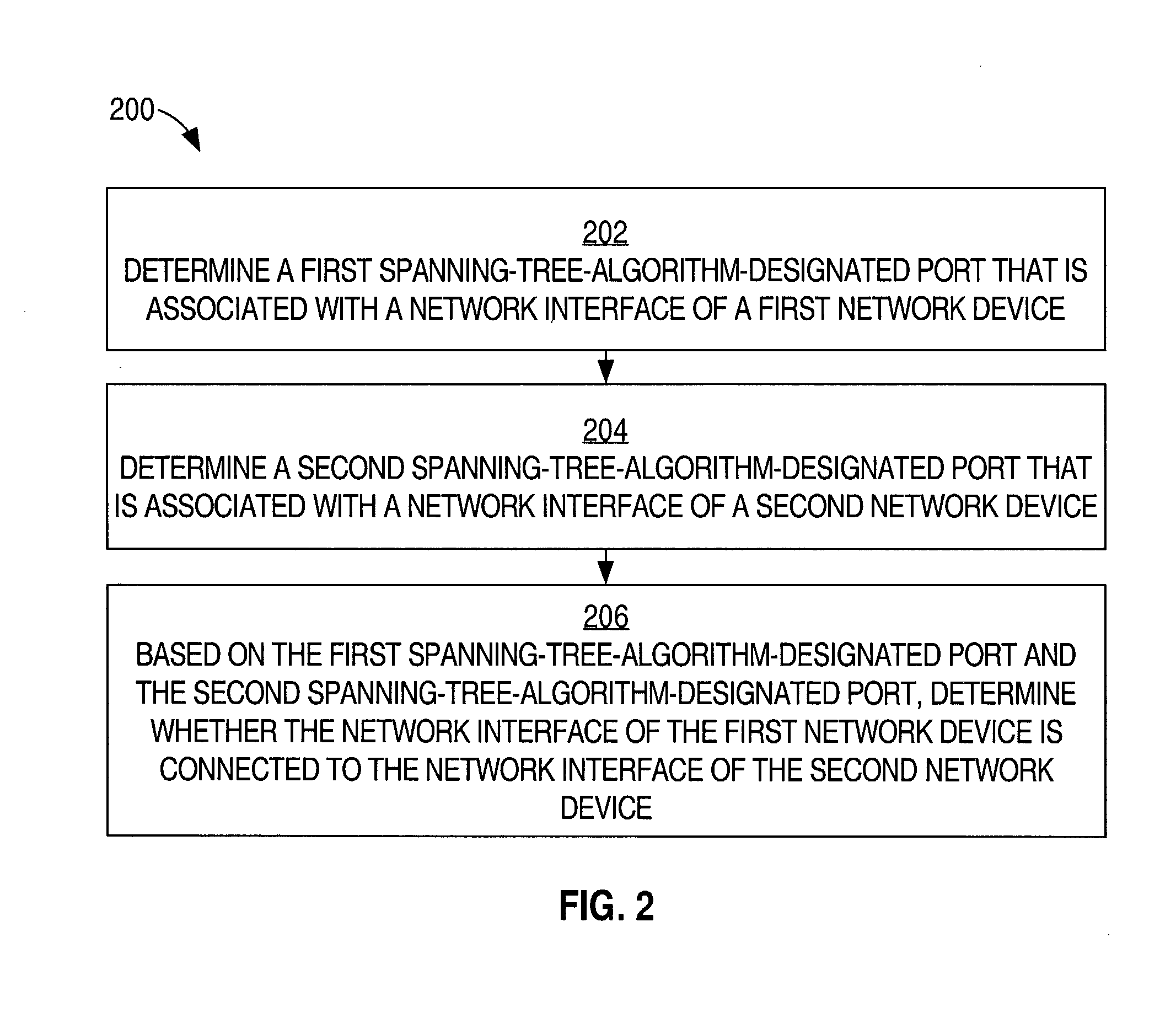
A method of determining a network topology based on Spanning-tree-Algorithm-designated ports is disclosed. A first Spanning-tree-Algorithm-designated port that is associated with a network interface of a first network device is determined. A second Spanning-tree-Algorithm-designated port that is associated with a network interface of a second network device is determined. Based on the first designated port and the second designated port, it is determined whether the network interface of the first network device is connected to the network interface of the second network device.

Description

FIELD OF THE INVENTION[0001]The present invention generally relates to computer network topology. The invention relates more specifically to a method and apparatus for determining a network topology based on Spanning-tree-Algorithm-designated ports.BACKGROUND OF THE INVENTION[0002]The approaches described in this section could be pursued, but are not necessarily approaches that previously have been conceived or pursued. Therefore, unless otherwise indicated herein, the approaches described in this section are not prior art to the claims in this application and are not admitted to be prior art by inclusion in this section.[0003]Computers and other devices equipped with network interface hardware may be connected together to form a network that allows the devices to communicate data with each other. An example of such a network is a local area network (LAN). A LAN may be composed of several different LAN segments. All devices connected to a given LAN segment receive all of the data co...

Claims


Application Information

Patent Timeline
IPC IPC(8): H04L12/28
CPCH04L12/66H04L45/00H04L45/02H04L45/04H04L45/48
Inventor SANKARAN, GANESH C.
Owner CISCO TECH INC
Why Eureka
Try Eureka