Eureka AIR delivers breakthrough ideas for toughest innovation challenges, trusted by R&D personnel around the world.

Distribution scheme for distributing information in a network

a network and information technology, applied in the field of distribution schemes for network parameters, can solve the problems of limiting the number of base stations in the run, unable to centralize the location of a combining point, e.g. mdc point, and the inability to update traffic to become a source of network congestion itself, so as to achieve efficient and scalable distribution

Active Publication Date: 2005-11-17
WSOU INVESTMENTS LLC
View PDF15 Cites 20 Cited by
  • Summary
  • Abstract
  • Description
  • Claims
  • Application Information

AI Technical Summary

Benefits of technology

[0008] It is therefore an object of the present invention to provide a method and network node for distributing a network parameter information, by means of which a more efficient and scalable distribution can be provided.
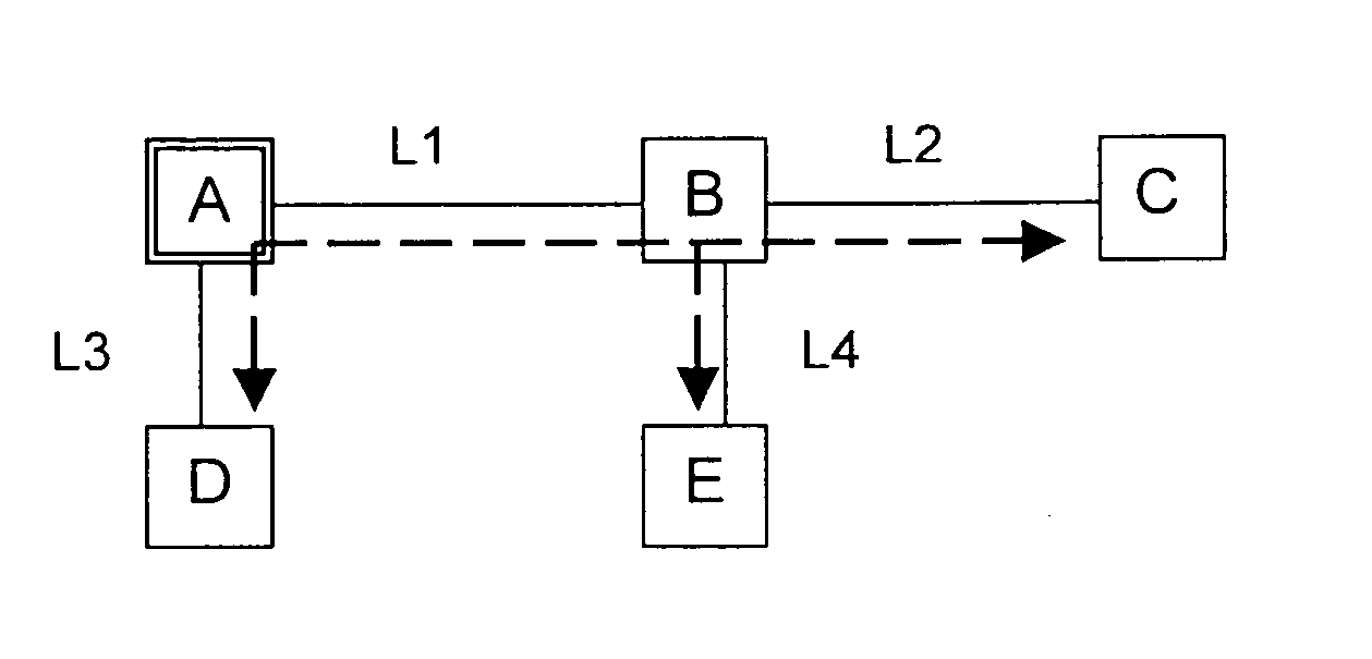
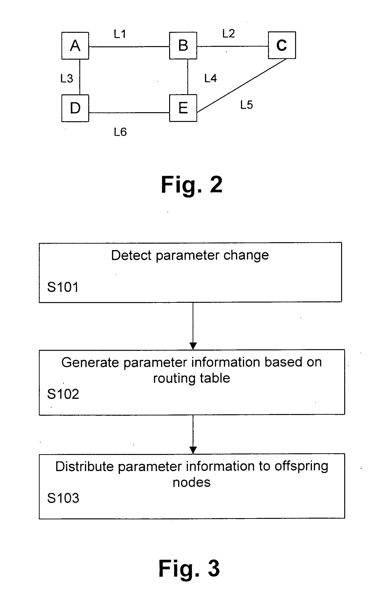
[0016] Due to the distribution according to the spanning tree, one parameter change only invokes as many updating messages or packets as a small fraction of the total number of links in the transmission network. Hence, updating messages or packets initiated by a given node only travel through a given spanning tree of the transmission network. Utilizing the topology information of the network, the delivery of the parameter information can be optimized and improved e.g. to avoid the conventional flooding scheme. Thereby, the updating message or packet traffic can be reduced dramatically as compared to the traffic of the flooding scheme under the same condition.

Problems solved by technology

This enables new functions such as soft handover, but also causes strict requirements on power control.
Therefore, a location of a combining point, e.g. MDC point, can no longer be centralized for all base stations in the RAN.
Thus, updating traffic may become a source of network congestion itself.
Furthermore, the flooding scheme is not scalable with an increase of the dimension of the RAN.

Method used


Image

  • Distribution scheme for distributing information in a network
  • Distribution scheme for distributing information in a network
  • Distribution scheme for distributing information in a network

Examples


Embodiment Construction

[0030] The preferred embodiment will now be described on the basis of a new RAN network architecture for providing access to an IP network.

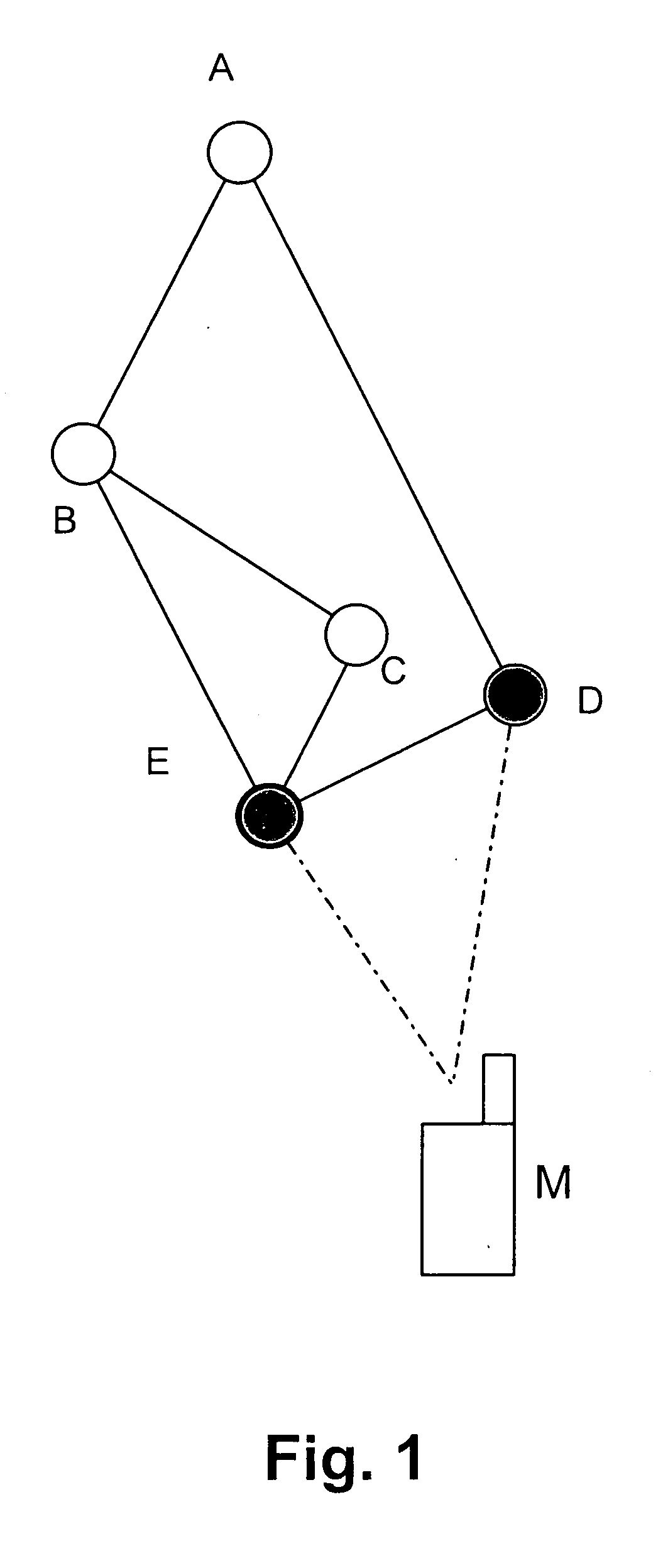
[0031] According to FIG. 1, a mobile terminal M is connected to a RAN via two redundant transmission paths indicated by respective dash-dot lines. The RAN architecture comprises a plurality of network nodes A to E, e.g. IP-based base stations, wherein the shaded nodes D and E are currently connected to the mobile terminal M via the redundant transmission paths. In particular, the network node E indicated with the bold circle is used as the serving base station, i.e. the base station terminating the core network interfaces data stream, and performing Radio Resource Management (RRM) functions like scheduling, power control and the like. In contrast thereto, the other shaded base station D is used as a drift base station providing only resources and radio L1 layer functions for the respective connections to the mobile terminal M.

[0032] In the RAN ...


PUM


Abstract

The present invention relates to a method and network node for distributing a network parameter information among network nodes of a transmission network. A spanning tree of routing paths corresponding to the shortest paths from said network node to other nodes is determined based on a topology information of the transmission network, and is used to distribute the network parameter information from the network node to the other network nodes. Thereby, the updating message or packet traffic can be reduced dramatically as compared to the conventional flooding scheme.

Description

FIELD OF THE INVENTION [0001] The present invention relates to a method and network node for distributing a network parameter information, which may consist of link utilization, node utilization, Macro Diversity Combining (MDC) load, and any other Quality of Service (QoS) related parameters associated to a given network node, among network nodes of a transmission network such as a radio access network for providing a connection to an Internet Protocol (IP) based a core network. In particular, the distributed network parameter information may be used by a procedure for selecting an MDC point in the radio access network (RAN). BACKGROUND OF THE INVENTION [0002] In a Code Division Multiple Access (CDMA) based cellular network all users in the same cell or in different cells may share the same frequency spectrum simultaneously. In spread spectrum transmission, the interference tolerance enables universal frequency reuse. This enables new functions such as soft handover, but also causes ...

Claims


Application Information

Patent Timeline
Patent Type & Authority Applications(United States)
IPC IPC(8): H04L45/02H04W28/18H04W40/02H04W40/24
CPCH04L45/02H04L45/12H04W40/246H04W28/18H04W40/02H04L45/48H04L45/03
Inventor TANG, HAITAOLAKKAKORPI, JANI
Owner WSOU INVESTMENTS LLC
Why Eureka
Eureka Blog
Learn More