Method for gaining time information and receiver for implementing the method

a time information and receiver technology, applied in the field of gaining time information and receiver for implementing the method, can solve the problems of increasing the computer effort and expense, short duration increase in the signal level of the time signal, and the tendency of conventional receivers for radio-controlled clocks to switch over too early, so as to prevent from contributing to an erroneous signal interpretation, gate out or filter out

Inactive Publication Date: 2008-05-06
ATMEL GERMANY +2
View PDF59 Cites 3 Cited by
  • Summary
  • Abstract
  • Description
  • Claims
  • Application Information

AI Technical Summary

Benefits of technology

[0029]It is a special advantage of the invention that the present time signal receiver and thus any radio-controlled clock has a larger system sensitivity because classic, typically very short noise impulses are effectively gated out or filtered out. Noise signals that, based on experience, occur frequently, can now be filtered out selectively and are thus prevented from contributing to an erroneous signal interpretation.
[0030]According to the invention the demodulated time signal particularly in the area of a second impulse, is now superimposed by significantly fewer noise signal components which assures a reliable decoding. Further, falsifications of the date bits lengths or durations which, in the worst case scenario, can lead to an erroneous decoding of the respective data bit, are significantly reduced. This features leads to an overall improved sensitivity of the receiver for a radio-controlled clock and thus to a better system sensitivity.
[0031]The present method can be implemented either by hardware or by software, which means that it can be realized in the most different receiver arrangements for radio-controlled clocks. The circuit according to the invention is also easily implemented by at least one memory, a counter stepped up or down by a reference clock signal and at least one evaluating unit. Due to its simplicity the present method and the respective circuit arrangement can be effectively yet economically implemented.
[0032]According to the invention the following step sequence is performed. The time signal is scanned, scanned values are intermediately stored, scanned values are read-out in the same sequence as they have been stored, and two neighboring scanned values are compared. No difference indicates no amplitude change. A difference indicates an amplitude change. A difference may be due to an amplitude change required for encoding the second impulse or impulses of the time signal. Alternatively, a difference may be due to a noise signal which is to be gated out so that the time signal will not show an amplitude change at this point of time. In order to distinguish between changes caused by encoding and those caused by noise, the durations of these changes are measured. One way of measuring the duration is by starting counting clock signal pulses with the start of a change and stop the counting when the change stops. Alternatively, these durations may be derived from a number of scanned values allocated to a detected amplitude change because each scanning step has a defined time duration. The evaluation unit compares the measured time duration with a predetermined duration (Δt). If the measured duration is shorter than (Δt), the respective change is gated out and not demodulated. If the measured duration is longer than (Δt) the longer duration amplitude change is demodulated and subsequently decoded by determining and evaluating the respective duration of a second impulse. The result is a time signal free of noise.
[0033]According to an advantageous embodiment of the invention, different telegrams of different time signal transmitters or the respective protocols may be stored in a memory, which may be separate from the memory for storing scanned values. These different telegrams or protocols may be stored for example in the form of a look-up table. The look-up table memory may be part of the radio-controlled clock or part of the clock's receiver. Additionally or alternatively, such telegrams or protocols may be implemented as hardware logic, for example in a PLD circuit or in an FPGA circuit. The predetermined time duration (Δt) or the predetermined number of scanning values will depend from the telegram of the respective received time signal.
[0034]It is preferred to determine the predetermined time duration (Δt) or the predetermined number of scanning values with reference to the shortest time duration that is determined by the telegram or encoding, particularly with reference to the shortest second impulse of the time signal. In this connection the duration of a preselected number of scanning values should be less than 50% of the shortest amplitude change as determined by the respective encoding protocol. Preferably, the maximum duration should be 25% of the shortest duration amplitude change that is part of the encoding. As an example, the protocol of the United States time signal transmitter WWVB comprises three different second impulse durations of 200 msec, 500 msec, and 800 msec. Thus, according to the invention all amplitude changes having a duration shorter than 100 msec should be gated out, particularly changes shorter than 50 msec should be gated out from the time signals received from WWVB. Similar considerations apply to other time signal transmitters, for example the German transmitter DCF-77 which transmits second impulses having a duration of 100 msec and 200 msec. Accordingly, change durations of 50 msec or 25 msec should be gated out or filtered out. Thus, these short duration changes will not be part of the demodulation.

Problems solved by technology

Frequently, noise signals are superimposed on received time signals which causes a problem because noise signals may disturb the time signal accuracy.
Even electrical components within the time signal receiver itself may cause noise.
If the noise impulses are present within the range of a second impulse, such noise signals may cause a short duration increase in the signal level of the time signal.
Problems occur, when time signals with such fluctuations are decoded.
As a result, an increased computer effort and expense is necessary for gaining the time information and for evaluating the gained information in order to be able to distinguish between amplitude reductions determined by the time protocol of the time signal on the one hand and noise caused amplitude changes such as reductions on the other hand.
Another problem is seen in the fact that conventional receivers for radio-controlled clocks have a tendency to switch over too early to the nominal signal level of the time signal when the second impulses are very long.
Such premature switch-over is undesirable since the second impulse or the respective amplitude reduction of the time signal is not yet completed.
The two above mentioned problems lead to a falsification of the duration of a second impulse or rather of the respective amplitude reduction of the time signals that needs to be evaluated.
Falsified second impulses can lead to a faulty decoding of the time signal which means that at least one data bit of the minute protocol has been incorrectly evaluated.
As a result, the time derived from the time signal would not be correct anymore.

Method used


Image

  • Method for gaining time information and receiver for implementing the method
  • Method for gaining time information and receiver for implementing the method
  • Method for gaining time information and receiver for implementing the method

Examples


Embodiment Construction

[0051]In the drawings all structurally or functionally equivalent elements and signals are designated with the same reference characters unless otherwise indicated.

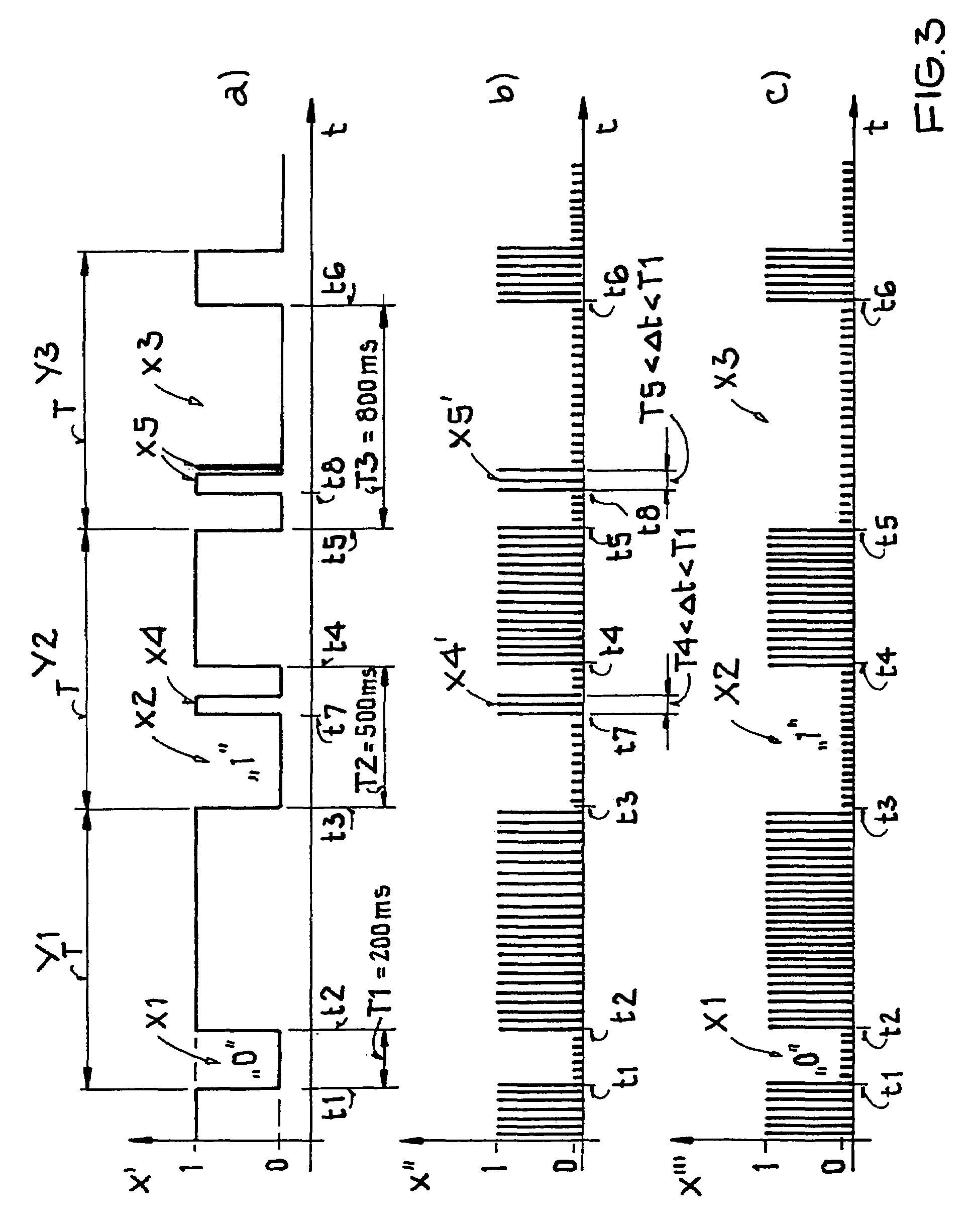
[0052]FIG. 3 shows a portion of a time signal transmitted by the United States time signal transmitter WWVB. This time signal diagram is used for explaining the invention. It should be noted that the illustration of FIG. 3 is not suitable for reproducing a special encoding. FIG. 3 is merely shown as an example. Further, the scale along the time axis t has been enlarged to provide a better overview.

[0053]The sections of FIG. 3 show three complete time frames Y1 to Y3 of the time signal X. The duration of each time frame Y1 to Y3 corresponds exactly to t=1000 msec. The time signal X transmitted by the transmitter WWVB comprises three different second impulses for the binary encoding. The respective amplitude changes are amplitude reductions X1 having a duration of t1=200 msec, X2 having a duration of t2=500 msec and X3 havi...


PUM


Abstract

Time signals transmitted by a time signal transmitter and received by a receiver are processed for gaining time information and for reducing demodulation errors to increase the demodulation certainty. For this purpose the following steps are performed in a time signal receiver: a) scanning of received time signals, b) storing of scanned values of the time signal, c) detecting from the scanned and stored values an amplitude change in said time signal, d) measuring the duration of any detected amplitude changes, e) evaluating the measured time durations relative to a predetermined time duration (Δt) and f) excluding from further processing amplitude changes that have a measured duration that is shorter than the predetermined duration. Amplitude changes of longer duration than (Δt) are demodulated and further processed. The receiver circuit is equipped to perform the foregoing steps, particularly in a radio-controlled clock.

Description

CROSS-REFERENCE TO RELATED APPLICATION[0001]This application is related to U.S. Application 11 / 045,441 filed on Jan. 28, 2005. The entire disclosure of the related application is incorporated herein by reference.PRIORITY CLAIM[0002]This application is based on and claims the priority under 35 U.S.C. §119 of German Patent Application 10 2004 004 375.2, filed on Jan. 29, 2004, the entire disclosure of which is incorporated herein by reference.FIELD OF THE INVENTION[0003]Time information is retrieved from received amplitude modulated time signals transmitted by a time signal transmitter. The received information is used to operate a radio-controlled clock or a receiver circuit of such a clock.BACKGROUND INFORMATION[0004]The radio-controlled transmission of time information is performed by transmitting so-called time signals by respective transmitters referred to herein as time signal transmitters or simply transmitter. The term “time signal” is intended to mean a transmitter signal of ...

Claims


Application Information

Patent Timeline
Patent Type & Authority Patents(United States)
IPC IPC(8): H04L27/00G01S13/00G04G5/00G04G21/04G04R20/08H04B1/18
CPCG04G5/002G04G7/023G04G21/04G04R20/08
Inventor HAEFNER, HORSTPOLONIO, ROLANDSAILER, HANS-JOACHIM
Owner ATMEL GERMANY
Why Eureka
Try Eureka