Optical access system

a technology of optical access system and optical access system, which is applied in the field of optical access system, can solve the problems of signal loss, periodic signal communication becoming impossible, and the distance between the ont and the olt not always fixed

Inactive Publication Date: 2008-05-06
HITACHI LTD
View PDF13 Cites 12 Cited by
  • Summary
  • Abstract
  • Description
  • Claims
  • Application Information

AI Technical Summary

Benefits of technology

[0012]In a second aspect of this invention to resolve the above problems, long-period frames that are X-number of times larger than the short-period frames are utilized, and the ranging timing fixed at a specified position on the long-period frame. The communication signals are then clustered into multiple short-period frames ahead of time at the transmitter, assembled as composite frames and transmitted. These composite frames are then disassembled at the receiver, attached to a 125 μs signal and transmitted towards the next communications device. Communication interruptions can then in this way be avoided by scheduling the transmission timing of these composite frames so as not to conflict with the ranging timing.
[0013]This invention can therefore provide an optical access system capable of transmitting signals requiring periodic transmission without interruptions in communication even during the ranging operation.

Problems solved by technology

In the PON system however, the distance between the ONT and OLT is not always a fixed distance.
The problem is that the ranging is performed and user signal is stopped for 250 μs, periodic signal communication becomes impossible and the signal is lost.

Method used


Image

  • Optical access system
  • Optical access system
  • Optical access system

Examples


Embodiment Construction

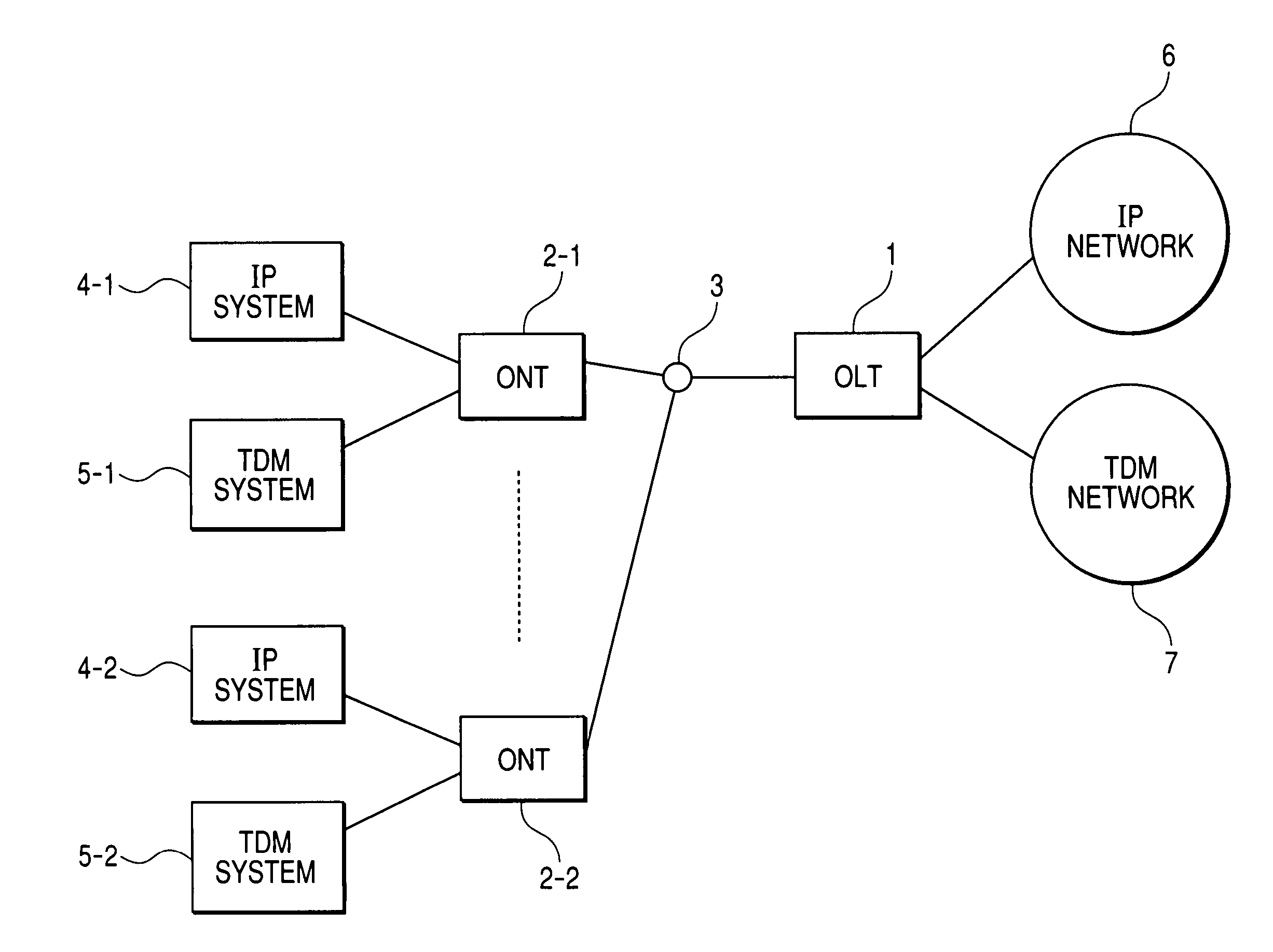
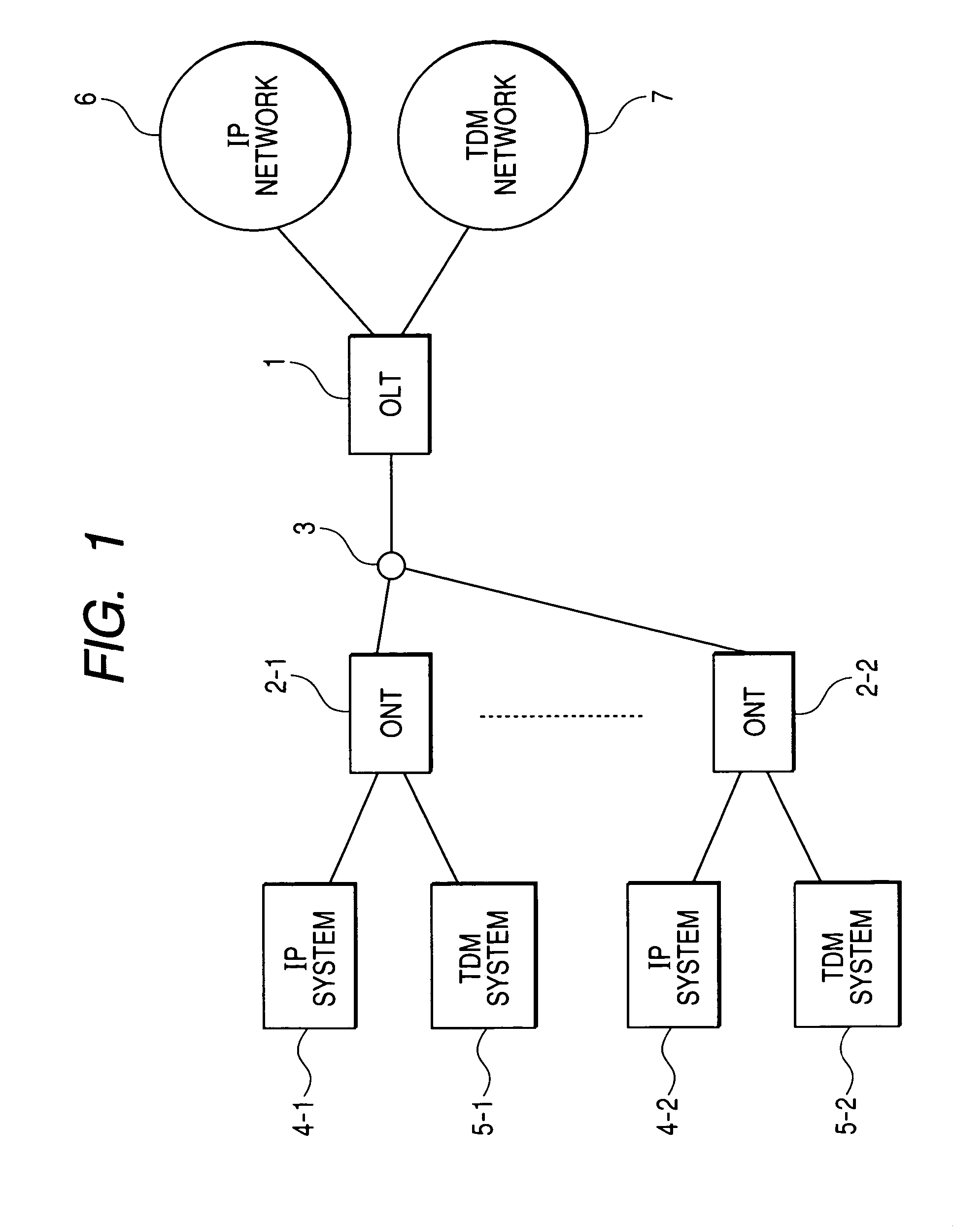
[0031]FIG. 1 is a drawing showing the first embodiment of the optical access network system of this invention. The optical access network system is configured between the OLT-1 and the ONT 2-1, ONT 2-2. The OLT connects to each ONT via a splitter 3. At least one among the ONT 2 is connected to the IP system 4 and the TDM system 5. The OLT connects to the IP network 6 and the TDM network 7. TDM signals from the TDM system 5 are stored into the TDM network 7 via the optical network. Signals from the IP system 4 are stored in the IP network 6 via the optical network.

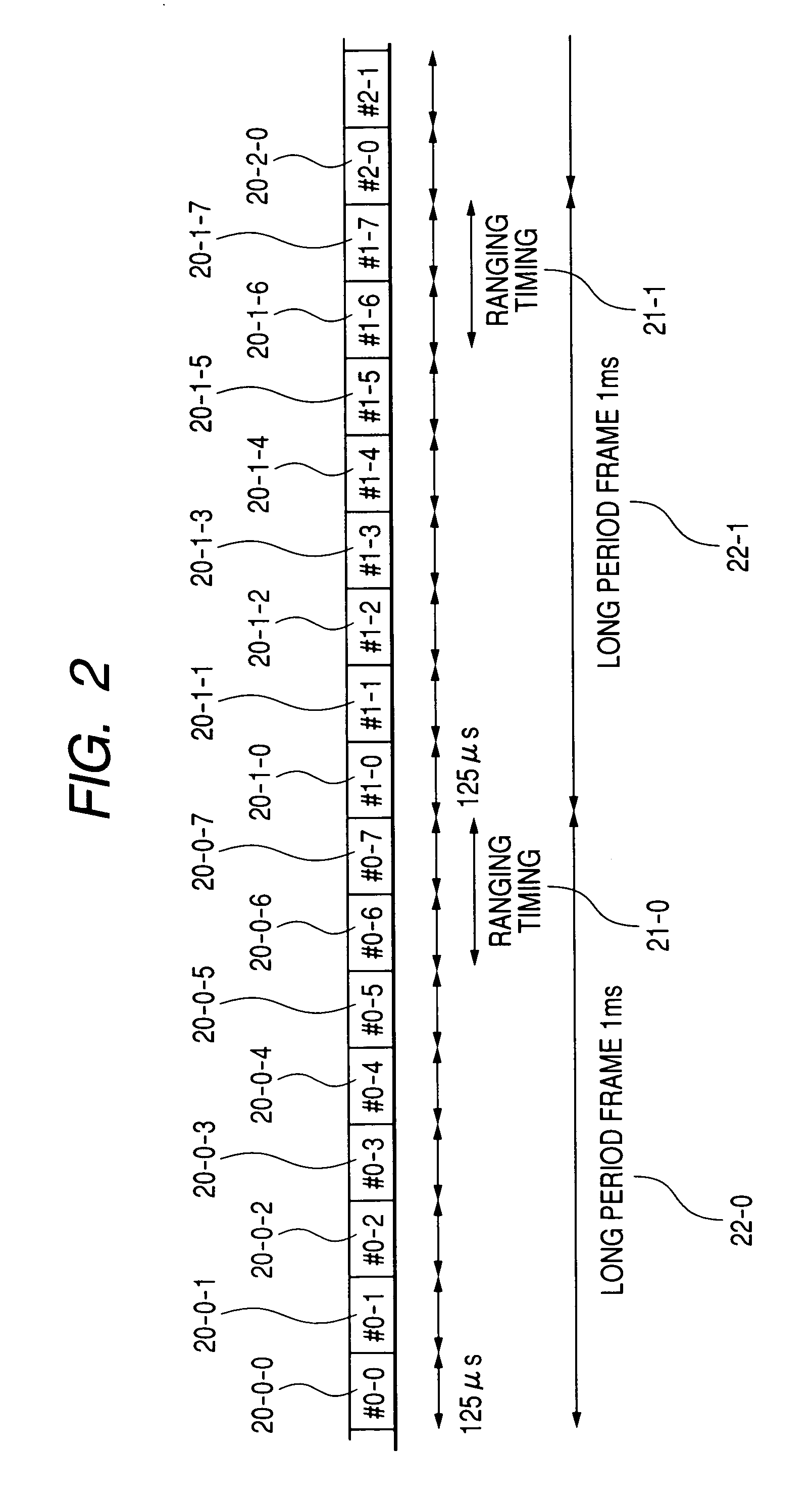
[0032]The ranging is described next using FIG. 13. Ranging is a process for measuring the distance between the OLT and ONT in order to correct the phase of the upstream signal. Ranging starts from the OLT and is performed by immediately returning the signal at each ONT. The ranging window 152 is the time in which ranging is performed and during this time, communication interruptions occur. In this invention, time-division m...


PUM


Abstract

An optical access system capable of avoiding cutoffs or interruption in the periodically transmitted signals that occur during the ranging time is provided. A first method to avoid signal cutoffs is to stop periodic transmit signals at the transmitter during the ranging period, and transmit all the periodic transmit signals together when the ranging ends, and buffer the signals at the receiver to prepare for ranging. A second method is to fix definite periods ahead of time for performing ranging, then cluster the multiple periodic transmit signals together in sets at the transmitter and send them, and then disassemble those sets back into signals at the receiver. The transmitting and receiving is then controlled so that the transmit periods do not overlap with the ranging periods. In this way an optical access system is provided that can send and receive signals requiring periodic transmissions without interruption even during ranging operation.

Description

CLAIM OF PRIORITY[0001]The present application claims priority from Japanese application JP 2005-219907 filed on Jul. 29, 2005, the content of which is hereby incorporated by reference into this application.FIELD OF THE INVENTION[0002]The present invention relates to an optical access system for communication between a subscriber residence and a communication provider station.BACKGROUND OF THE INVENTION[0003]Telephone subscriber networks and ADSL have been utilized in access networks for storing user stations in public communications networks for forwarding data such as audio or video. Moreover optical access systems have become more widespread in recent years.[0004]These optical access systems use a method for connecting the station and the subscriber in a one-to-one relationship, and a method for connecting in a one-to-x relationship. The PON (Passive Optical Network) method is known as one-to-x connection method.[0005]In the PON method, data communication is performed by sharing ...

Claims


Application Information

Patent Timeline
Patent Type & Authority Patents(United States)
IPC IPC(8): H04B10/00H04B10/272H04J3/00H04J14/08H04L12/44
CPCH04J3/1694H04J3/0682
Inventor SAKAMOTO, KENICHIASHI, YOSHIHIROKAZAWA, TOHRUNISHINO, RYOSUKETAKASE, MASAYUKIMIZUTANI, MASAHIKO
Owner HITACHI LTD
Why Eureka
Try Eureka