Fuel feed unit

a technology of fuel feed and unit, which is applied in the direction of liquid fuel feeder, machine/engine, separation process, etc., to achieve the effect of reducing the cost in design terms of reducing the annular gap in the volume flow reducing valve, being easy to produce, and being inexpensive to produ

Inactive Publication Date: 2008-05-13
SIEMENS AG
View PDF20 Cites 11 Cited by
  • Summary
  • Abstract
  • Description
  • Claims
  • Application Information

AI Technical Summary

Benefits of technology

[0007]This design means that as the delivery pressure of the fuel pump increases the delivery of fuel to the suction jet pump via the pump liquid line is maintained or restricted. The suction jet pump can therefore be designed for a low fuel pump delivery capacity. Should the delivery capacity of the fuel pump increase due to a rising demand requirement from the internal combustion engine, the volume flow reducing valve reduces the delivery of fuel to the suction jet pump by way of the pump fluid line. This serves to prevent any unnecessary delivery of fuel to the suction jet pump. This allows the fuel feed unit according to the invention to be of especially compact design. The small amount of fuel fed inside the fuel tank furthermore minimizes any permeation of fuel into the surroundings.
[0014]The need to arrange an additional cold starting valve, which when starting up the fuel pump keeps the pump fluid line closed until a minimum pressure has been reached, is readily avoided if the end of the piston assigned to the annular gap has a seal, which interacts with a seal seat in the duct.

Problems solved by technology

This means, however, that in most operating states the suction jet pump receives an unnecessarily large amount of fuel as pump fluid, which requires the use of an especially high-performance pump unit.

Method used


Image

  • Fuel feed unit
  • Fuel feed unit

Examples


Embodiment Construction

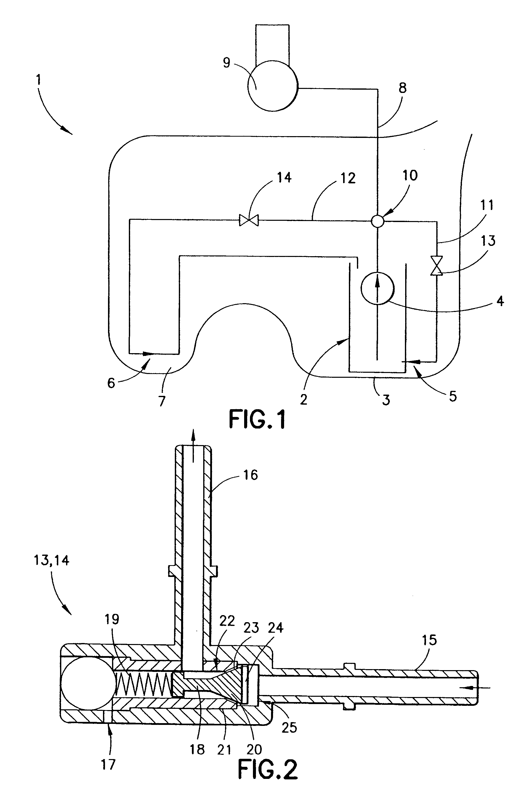
[0018]FIG. 1 shows a fuel tank 1 in the form of a saddle tank for a motor vehicle having a fuel feed unit 2 arranged therein. The fuel feed unit 2 has a fuel pump 4, drawing in fuel from a swirl pot 3 arranged in the bottom area of the fuel tank 1, and two suction jet pumps 5, 6 for filling the swirl pot 3. One of the suction jet pumps 6 is arranged in a chamber 7 of the fuel tank 1 separated from the swirl pot 3, whilst the other suction jet pump 5 fills the swirl pot 3 with fuel directly surrounding the former. From the delivery side of the fuel pump 4 a feed line 8 leads to an internal combustion engine 9 of the motor vehicle. The fuel pump 4 is controlled as a function of the demand of the internal combustion engine 9.

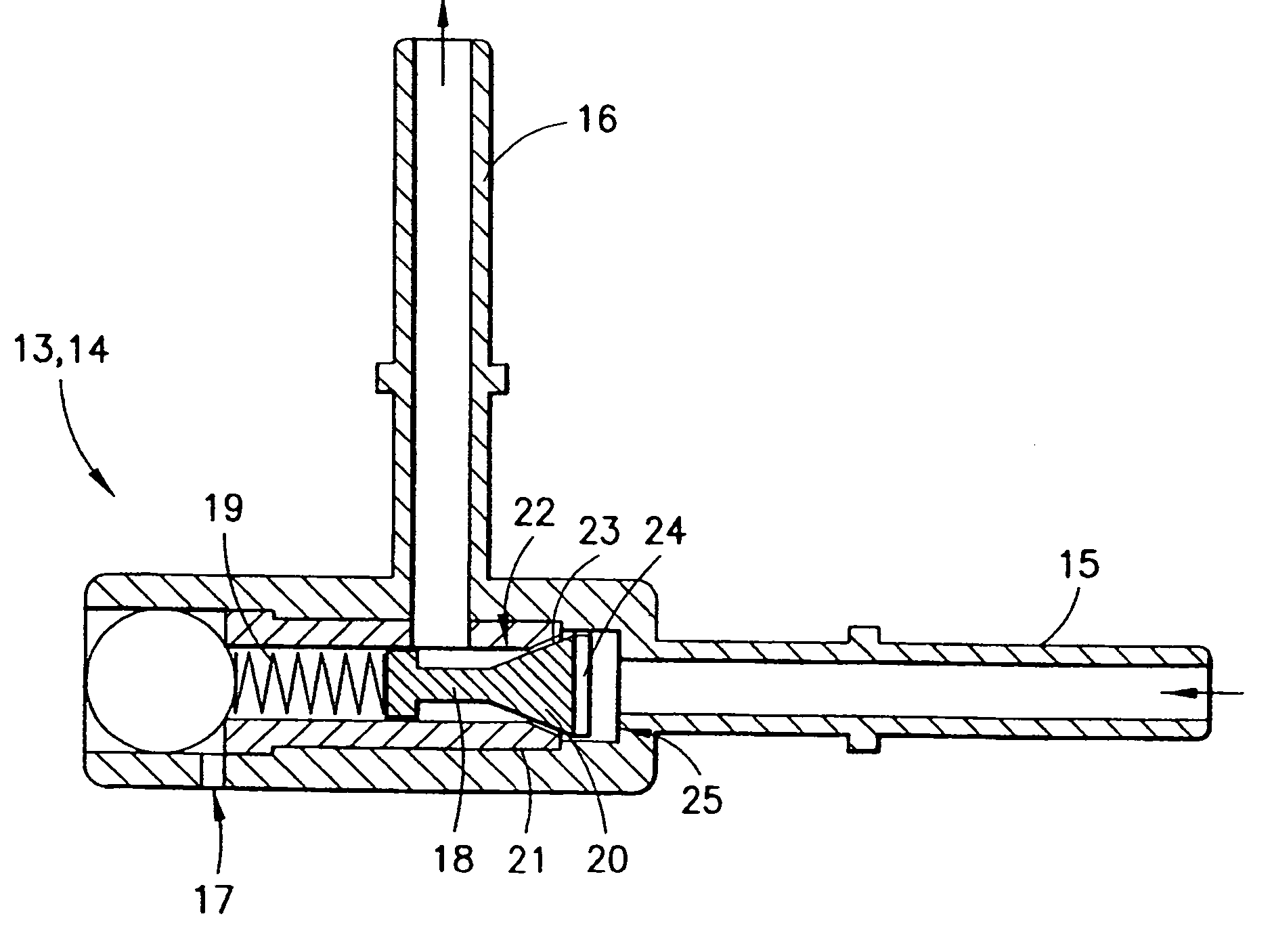
[0019]A distributor 10, to which pump fluid lines 11, 12 leading to the suction jet pumps 5, 6 are connected, is arranged in the feed line 8. These pump fluid lines 11, 12 serve to supply the suction jet pumps 5, 6 with fuel as working fluid. Volume flow reducing v...


PUM

PropertyMeasurementUnit
pressureaaaaaaaaaa
forceaaaaaaaaaa
delivery pressureaaaaaaaaaa

Abstract

The invention relates to a fuel feed unit (2) for a motor vehicle, comprising a volume flow reducing valve (13, 14) that is mounted in a pump fluid line (11, 12) leading to a suction jet pump (5, 6). Said volume flow reducing valve (13, 14) reduces the fuel volume flow supplied to the suction jet pump (5, 6) when the feed pressure of the fuel pump (4) increases, thereby avoiding unnecessary feed of fuel to the suction jet pump (5, 6).

Description

BACKGROUND OF THE INVENTION[0001]The invention relates to a fuel feed unit for feeding fuel from a fuel tank, having a fuel pump drawing in fuel from a swirl pot, a suction jet pump feeding fuel from the fuel tank into the swirl pot, and a pump fluid line led to the suction jet pump from the delivery side of the fuel pump.[0002]Such fuel feed units are commonly used in modern motor vehicles and are known in practice. The suction jet pumps are supplied with fuel by the fuel pump and feed fuel from the fuel tank into a swirl pot of the fuel feed unit, for example. In the known feed units fuel is delivered irrespective of whether fuel is present in the swirl pot.[0003]The suction jet pump, particularly in demand-controlled feed units, in which the delivery capacity of the fuel pump is controlled as a function of the fuel demand of an internal combustion engine of the motor vehicle, is designed in such a way that it delivers sufficient fuel even in the event of a low delivery pressure o...

Claims


Application Information

Patent Timeline
Patent Type & Authority Patents(United States)
IPC IPC(8): F02M37/04B60K15/077F02M37/02F02M37/10
CPCB60K15/077F02M37/025F02M37/106Y10T137/86075
Inventor DICKENSCHEID, LOTHAR
Owner SIEMENS AG
Why Eureka
Try Eureka