
Structure for protecting brake pedal from impact

a technology for protecting the brake pedal and the structure, which is applied in the direction of roofs, mechanical control devices, tractors, etc., can solve the problems of increasing the weight of the vehicle, inflicting injury on the driver, and depreciating the fuel consumption ra

Active Publication Date: 2008-05-13
HYUNDAI MOBIS CO LTD
View PDF6 Cites 2 Cited by
  • Summary
  • Abstract
  • Description
  • Claims
  • Application Information

AI Technical Summary

Benefits of technology

[0014]Therefore, the present invention has been made in view of the above problems, and it is an object of the present invention to provide a structure, for protecting a brake pedal from impact, comprising a supporter installed on a cowl crossbar positioned adjacent to the brake pedal, in which the supporter supports a brake pedal arm from moving toward a driver's seat when a traffic accident occurs, thereby protecting a driver from injury caused by the brake pedal.
[0015]In accordance with the present invention, the above and other objects can be accomplished by the provision of a structure for protecting a brake pedal from impact, comprising: a cowl crossbar, for a vehicle, provided with a pair of connection holes separated from each other, a supporter provided with a pair of converged brackets provided with connection holes coupled with the connection holes of the cowl cross bar using bolts; and supporting protrusions, formed on an end of the supporter, for preventing the brake pedal from moving.
[0016]The structure for protecting the brake pedal from impact comprises the supporter, including the supporting protrusions, installed on the cowl crossbar, so that the brake pedal is supported by the supporter and is thus impeded from moving toward a driver's seat when a vehicle accident occurs, thereby protecting a driver from injury—caused by from the movement of the brake pedal.

Problems solved by technology

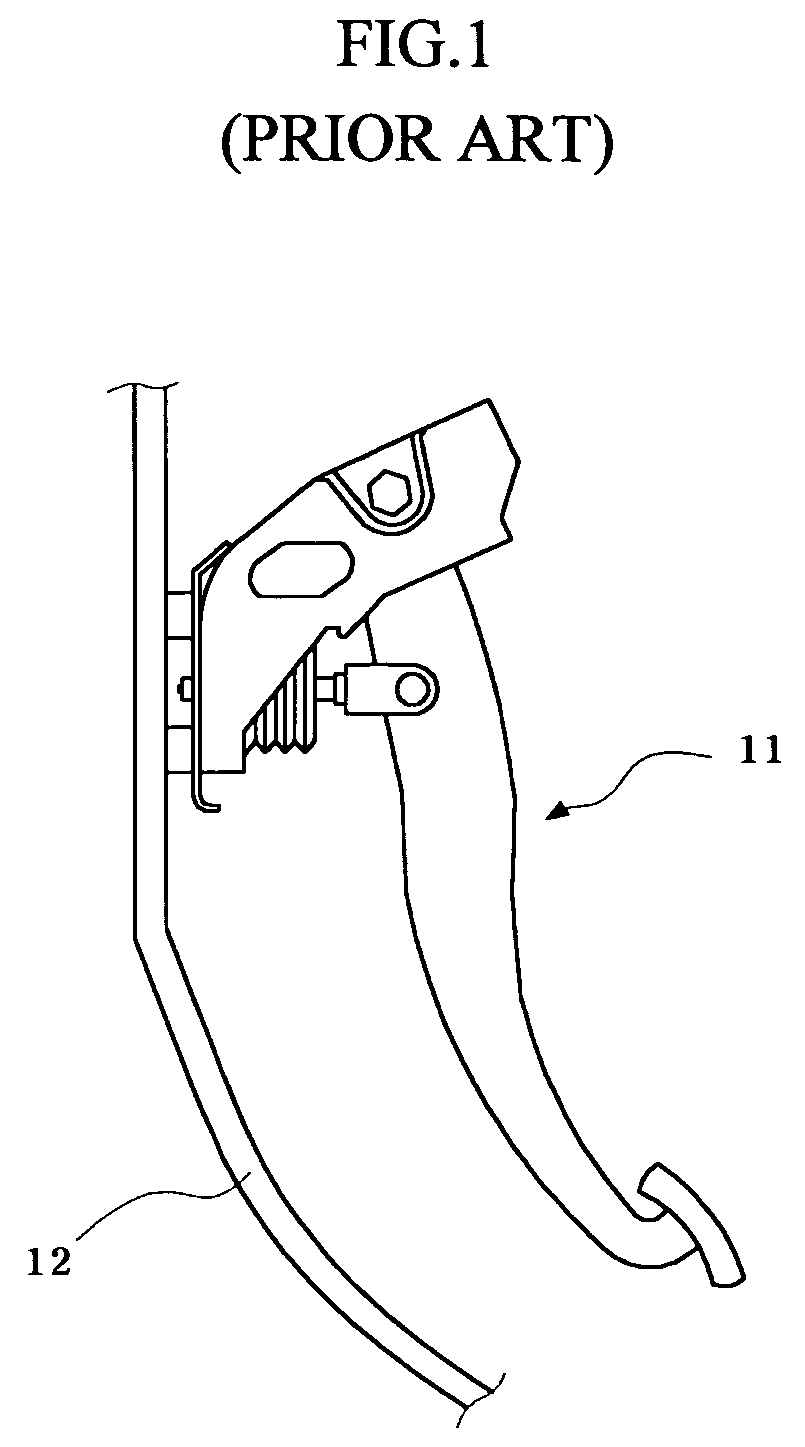
The brake pedal 11, having moved toward the driver's seat, may easily hits a driver's ankle or shin, thereby inflicting injury upon the driver.
However, the increase of the thickness of the dash panel 12 necessary to mitigate the aforementioned problem increases the weight of the vehicle, thereby depreciating the rate of fuel consumption.

Method used


Image

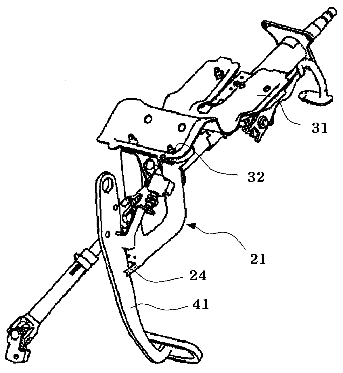
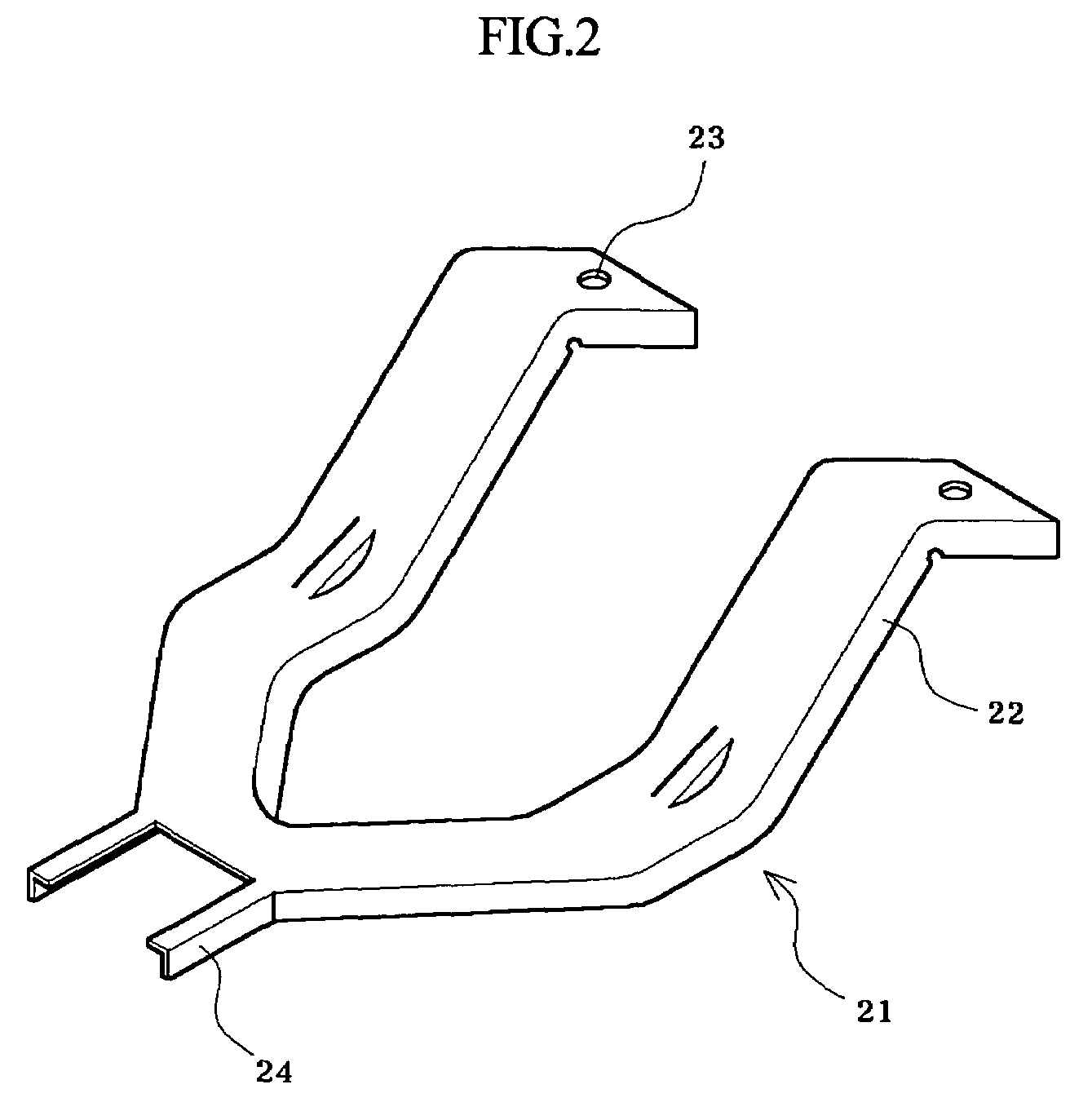
  • Structure for protecting brake pedal from impact
  • Structure for protecting brake pedal from impact
  • Structure for protecting brake pedal from impact

Examples


Embodiment Construction

[0021]Now, a preferred embodiment of the present invention will be described in detail with reference to the annexed drawings.

[0022]The following description made in conjunction with the preferred embodiment of the present invention has been made only for a better understanding of the present invention. Some parts in this embodiment are substantially the same as those in the prior art and are thus denoted by the same reference numerals even though they are depicted in different drawings.

[0023]FIG. 2 is a schematic view illustrating a supporter in accordance with the present invention, and FIG. 3 is a schematic view illustrating installation of the supporter of FIG. 2 on a crossbar.

[0024]As shown in FIGS. 2 and 3, a supporter 21 is installed on one end of a cowl crossbar 31 installed in a vehicle in a transverse direction.

[0025]The supporter 21 has a structure such that a pair of brackets 22 separated from each other are converged at their ends, and a connection hole 23 is formed thr...


PUM


Abstract

A structure for protecting a brake pedal of a vehicle from impact, the vehicle having a cowl crossbar provided with a pair of spaced apart connection holes, includes a supporter provided with a pair of converged brackets, each of the converged brackets provided with connection holes couplable with the connection holes of the cowl crossbar by using bolts, and a plurality of supporting protrusions provided on an end of the supporter, the supporting protrusions preventing the brake pedal from moving toward an occupant of the vehicle in the event of a collision.

Description

RELATED APPLICATIONS[0001]The present disclosure relates to subject matter contained in Korean Application No. 10-2004-43184, filed on Jun. 11, 2004, which is herein expressly incorporated by reference its entirety.BACKGROUND OF THE INVENTION[0002]1. Field of the Invention[0003]The present invention relates to a structure, for protecting a brake pedal from impact, comprising a supporter installed on a cowl crossbar installed on a vehicle frame in a transverse direction for supporting an instrument panel, in which the supporter is located at a position adjacent to a brake pedal arm so that the supporter prevents the brake pedal from being pushed toward a driver's seat when a traffic accident occurs, thereby protecting a driver from injury.[0004]2. Description of the Related Art[0005]Generally, brake systems serve to decelerate or stop a vehicle in motion, and simultaneously to maintain a parking state of the vehicle.[0006]Of the brake systems, a foot brake, which is manipulated by a ...

Claims


Application Information

Patent Timeline
Patent Type & Authority Patents(United States)
IPC IPC(8): B60K28/10G05G1/00B60R21/09B60R21/11B60T7/06
CPCB60R21/09B60T7/065Y10T74/20528B60T7/06
Inventor NOH, JI-YOUN
Owner HYUNDAI MOBIS CO LTD
Learn More