Sharpener attachment for rotary tool

a technology for rotary tools and sharpeners, which is applied in the direction of turning tools, planing/slotting tools, other manufacturing equipment/tools, etc., can solve the problems of difficult to maintain a constant angle of the sharpening tool with respect to the sharpening surface, and the manual sharpening of the cutting tool by repeated stroking over an abrasive stone or other abrasive surface is very time-consuming, and achieves fast sharpening of cutting

Inactive Publication Date: 2002-05-16
BLANTON DEAN
View PDF0 Cites 3 Cited by
  • Summary
  • Abstract
  • Description
  • Claims
  • Application Information

AI Technical Summary

Benefits of technology

0015] The design of the present invention provides a cost-effective way to very quickly sharpen cutting implements and produce an extremely high quality cutting edge. The design of the present invention produces a cutting edge having a bevel of the desired angle, while squaring up blade edges. In addition, the sharpening attachment may be used with rotary tools that are typically available at construction sites, cabinet shops, furniture shops, home work shops and boat building sites, eliminating the need to provide a separate sharpening apparatus for sharpening cutting tools that are used at the construction site. The sharpener attachment quickly sharpens chisels and plane blades, and eliminates the need for time consuming hand sharpening. The attachment can be attached to a rotary tool in a short period of time. The limited number of parts associated with the attachment makes the sharpener very economical to produce and makes assembly and disassembly very easy. The attachment is lightweight and portable and provides both coarse and fine sharpening.

Problems solved by technology

Maintaining a constant angle of the tool being sharpened with respect to the sharpening surface is very difficult, because the tool must be stroked across the stone surface while maintaining substantially constant pressure between the edge and the stone.
Manual sharpening of a cutting tool by repeated stroking over an abrasive stone or other abrasive surface is very time consuming.

Method used


Image

  • Sharpener attachment for rotary tool
  • Sharpener attachment for rotary tool
  • Sharpener attachment for rotary tool

Examples


first embodiment

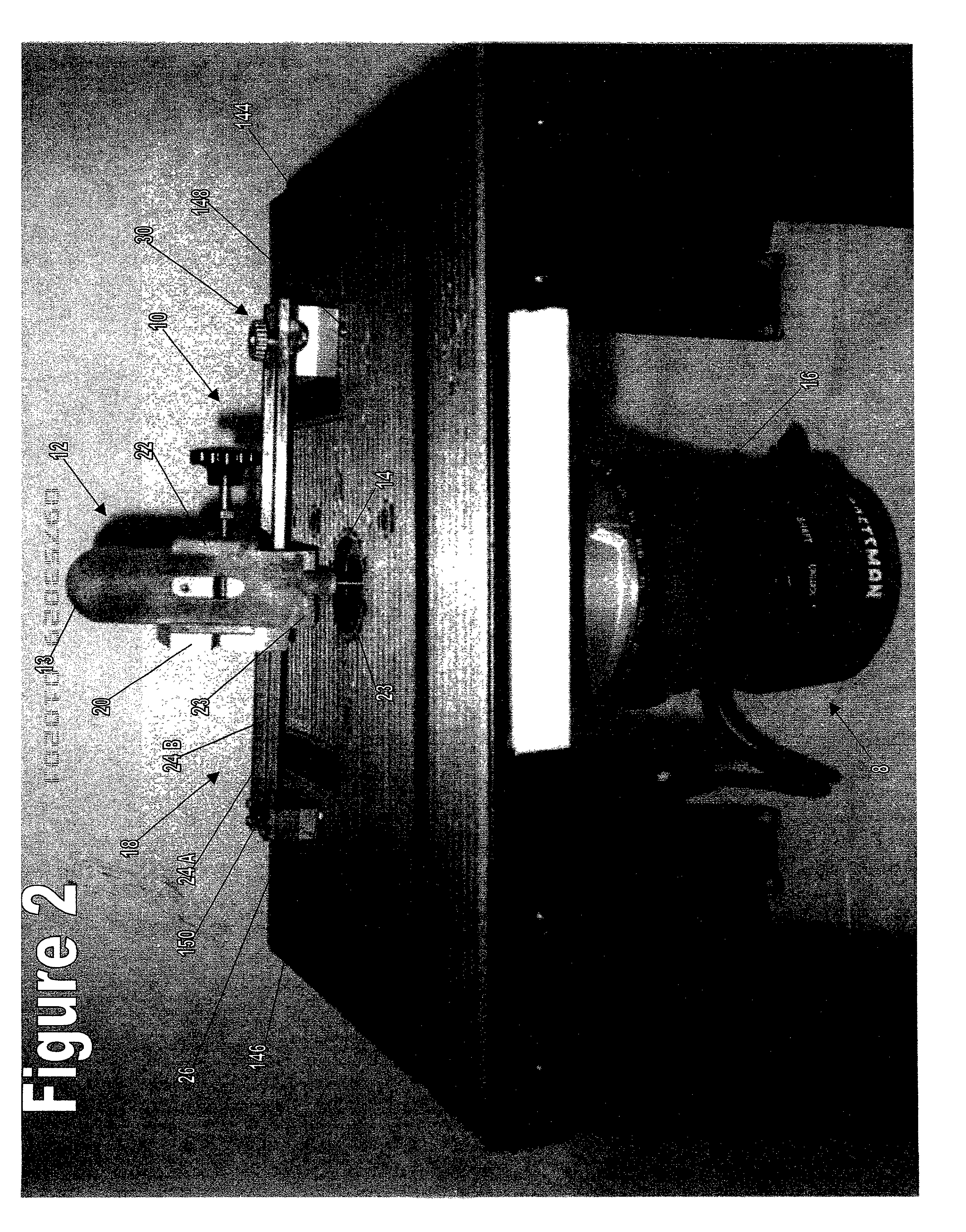
[0052] Referring to FIGS. 2 and 3, the sharpening attachment 10 is used with a router 8 in the exemplary embodiment. In a first embodiment, shown in FIG. 2, a router table 144 is modified such that the sharpening attachment 10 may be mounted to the router table 144. In this embodiment, a hole 146 and an arcuate slot 148 are cut in the router table 144 for attachment of the sharpening attachment 10. The radius of the arc that defines the arcuate slot 148 is equal to the distance between the large clearance hole 40 in the stationary end block 26 and the threaded hole 46 in the pivot block 28. In the exemplary embodiment, the stationary end block 26 is connected to the router table 144 by a hex head cap screw 150 that extends through the stationary end block 26 and the hole 146 in the router table 144. A locking knob 126c is secured to the screw 150 to secure the connection. The connection between the stationary end block 26 and the router table 144 is such that the stationary block is...

second embodiment

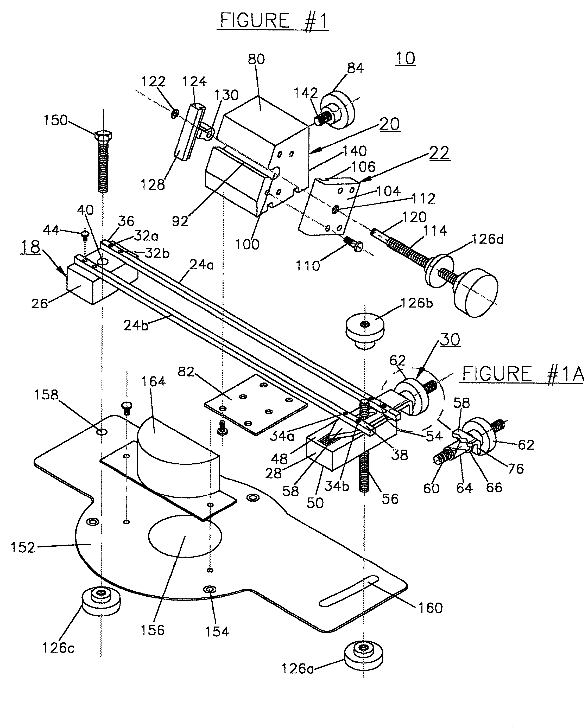
[0054] Referring to FIG. 3, in a second embodiment, the sharpening attachment 10 includes a mounting plate 152 that allows the sharpening attachment 10 to be connected directly to the router 8. Referring to FIG. 1, the router mounting plate 152 is a large flat plate which includes three countersunk holes 154 that allow for attachment to a router 8 and a center hole 156 that allows the rotating bit 14 of the router 8 to extend through the mounting plate 152. The mounting plate 152 includes a hole 158 and an arcuate slot 160. The sharpening attachment 10 is mounted to the mounting plate 152 in generally the same manner it is mounted to a router table 144 having a hole 146 and an arcuate slot 148. The hex head cap screw 150 is inserted through the hole 158, the coarse adjusting stud 56 is inserted through the slot 160 and the cap screw 150 and the stud 56 are fastened to the mounting plate 152 with locking knobs 126.

[0055] In the exemplary embodiment, the bit 14 is coupled to the route...


PUM

PropertyMeasurementUnit
angleaaaaaaaaaa
lateral movementaaaaaaaaaa
angleaaaaaaaaaa

Abstract

A sharpening attachment for sharpening cutting implements with a rotating bit of a tool. The sharpening attachment includes a guide, a mount and a clamp. The guide is adapted for attachment to a rotary tool. The mount is connected to the guide, such that the mount is laterally movable along the guide. The clamp clamps the cutting implement to the mount. Movement of the mount along the guide brings the cutting implement into contact with the rotating bit.

Description

[0001] The present application is a continuation-in-part of U.S. patent application entitled "Sharpener Attachment for Rotary Tool" filed Nov. 15, 2000, filed under Express Mail Label No. EL391520602US.[0002] The present invention relates to tool sharpening apparatuses, and more particularly, is directed to a sharpener attachment for a router or similar rotary tool.[0003] A number of cutting tools include cutting edges that must be kept free from surface infections, such as burrs, nicks and gouges. Such cutting tools which need to be free from surface imperfections include chisels, planar blades, scrapers, knife members of planar machines and knife members of joiner machines. When surface imperfections are present on the cutting edge of tools used to remove wood from a work piece, the surface imperfection can gouge the wood surface, requiring additional sanding to be performed to obtain an acceptable appearance of the work piece.[0004] It is known in the prior art to remove burrs an...

Claims


Application Information

Patent Timeline
Patent Type & Authority Applications(United States)
IPC IPC(8): B24B1/00B24B3/34
CPCB24B3/34B24B1/00
Inventor BLANTON, DEAN
Owner BLANTON DEAN
Why Eureka
Try Eureka