Electrical Equipment Receptacle Cover

Inactive Publication Date: 2010-03-11
SAF T GARD INT
View PDF4 Cites 0 Cited by
  • Summary
  • Abstract
  • Description
  • Claims
  • Application Information

AI Technical Summary

Benefits of technology

[0007]The invention is characterized by a cover formed of relatively soft rubber material of generally cylindrical configuration having an open end adapted to be slidably positioned over the projecting receptacle portion of an electrical equipment box. The cover includes a closed end spaced at a distance from the open end such that the cover encloses the receptacle portion when the cover is positioned thereover. The cover is formed with a pair of generally rectangular shaped extension portions disposed along opposite sides of the elongate length of the cover, each extension portion having a respective open end coextensive with the open end of the cover, and a closed end spaced beyond the plane of the closed end of the cover. The configuration of the cover and the closed ends of the extension portions is such that, when the cover is positioned over the receptacle portion of the electrical equipment box, any sharp and / or projecting portions thereof are prevented from causing injury to a person who comes in contact with the receptacle.

Problems solved by technology

The projecting receptacles, as well as the somewhat sharp edged fasteners associated therewith, have been known to present a safety hazard for workers who regularly function and perform operations around and about the electrical equipment during normal service activities.
The receptacle and associated fastener parts commonly are formed of metal or other rigid material and, when accidentally bumped or scraped against by a worker, can result in various degrees of injury.

Method used


Image

  • Electrical Equipment Receptacle Cover
  • Electrical Equipment Receptacle Cover
  • Electrical Equipment Receptacle Cover

Examples


Embodiment Construction

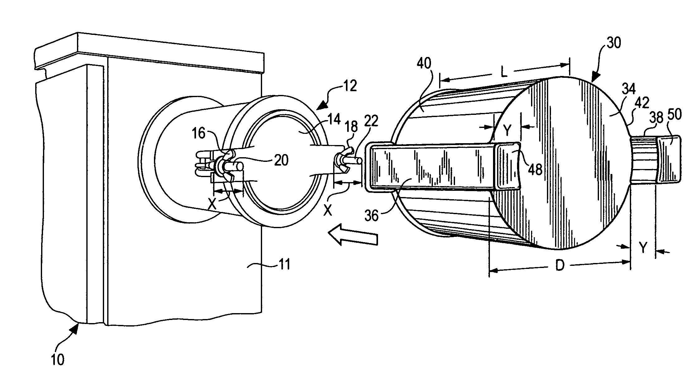
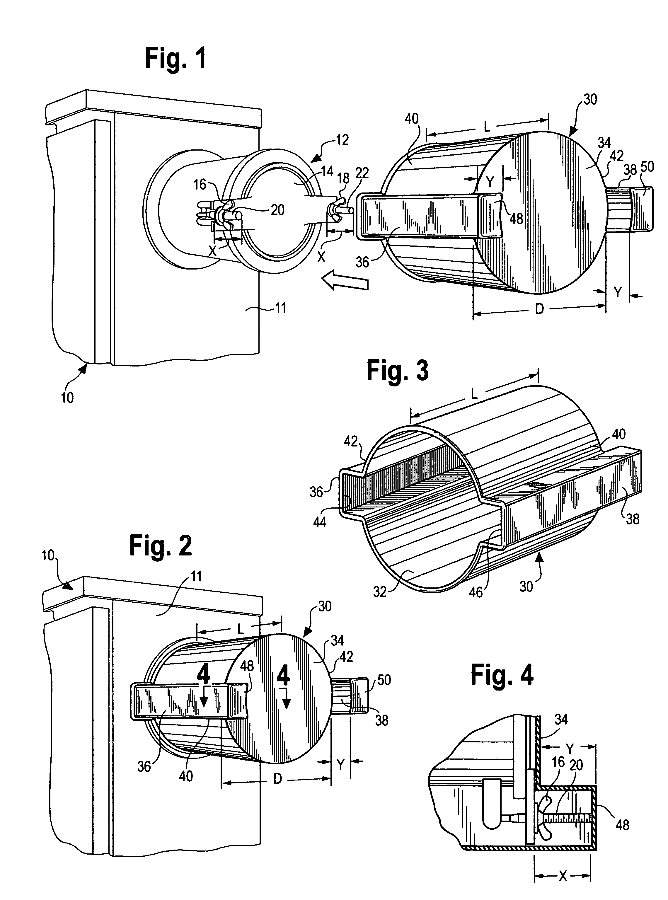
[0016]Referring to the drawings, FIG. 1 illustrates an electrical equipment distribution panel box 10 of the type commonly used in outdoor installations, such as for cell telephone towers. Although reference is made herein to an electrical equipment box of the type used with a cell telephone tower, it is to be understood that such equipment for use with any type of installation is contemplated for use in connection with the invention herein; the illustrated panel box 10 and its associated elements are one example only of the type of equipment with which the invention is adapted for use.

[0017]The electrical equipment retained within the panel box 10 for operating the associated equipment, i.e., a cell telephone tower, usually is supplied with power provided by a utility company by conventionally associated power lines (not shown). In the event that the power provided to the electrical equipment by a utility company becomes interrupted, such as by damaging storms or by other types of ...


PUM


Abstract

A soft rubber protective safety cover for positioning over a projecting receptacle portion of an electrical equipment box to minimize the safety hazard caused by such projecting portion. The cover is of generally cylindrical configuration with oppositely disposed generally rectangular portions positioned along the elongate dimension of the cover to encapsulate the receptacle when the cover is in position thereover so as to prevent sharp and / or projecting portions thereof from causing injury to a person who comes in contact with the receptacle.

Description

BACKGROUND OF THE INVENTION[0001]1. Field of the Invention[0002]This invention relates generally to covers for electrical equipment receptacles, and more particularly, to such covers intended to be positioned over protruding receptacle portions of heavy duty electrical equipment so as to minimize a safety hazard caused by such protruding receptacle portions.[0003]2. Description of the Related Art[0004]Electrical equipment of the type usually used in outdoor installations, such as for cell telephone towers, commonly includes a distribution panel box to retain electrical components of the equipment. It also is common for such panel boxes to have as a component thereof a receptacle intended to receive, when needed, a plug connector intended to supply auxiliary power to the cell tower for its continued operation in the event that the usually applied utility company power supply is interrupted. The receptacle positioned on many such panel boxes is in the form of a projecting adapter of g...

Claims


Application Information

Patent Timeline
IPC IPC(8): H01L23/28
CPCH02B3/00H02B1/50
Inventor RIVKIN, RICHARD A.
Owner SAF T GARD INT
Why Eureka
Try Eureka