
Vehicular mirror with slip clutch for jack screw actuator

Inactive Publication Date: 2008-05-13
MAGNA MIRRORS OF AMERICA
View PDF24 Cites 16 Cited by
  • Summary
  • Abstract
  • Description
  • Claims
  • Application Information

AI Technical Summary

Benefits of technology

[0008]A vehicular mirror system comprises a reflective element having a mounting portion thereon, an actuator operably interconnected to the reflective element for controlling the tilt of the reflective element, wherein the actuator is operable in a normal range of travel, and a clutch associated with the actuator for operation of the actuator in a first mode and a second mode, wherein in the first mode the actuator moves in a normal mode of operation and actuates the tilt of the reflective element, and wherein in the second mode the actuator is placed in an impeded mode of operation and the clutch allows the actuator to slip and prevent damage thereto. One of the mounting portion and the actuator can comprise a socket, and the other of the mounting portion and the actuator can comprise a ball. The ball can be snap-fit within the socket.

Problems solved by technology

However, this slippage is typically accompanied by a “clicking” sound as the ratchet mechanism is engaged.
This clicking sound is frequently interpreted as a performance defect or the result of poor quality, or it can be interpreted as a failure of the actuator, motivating the vehicle owner to seek maintenance that may be unnecessary.
Additionally, in mirrors having a positional memory feature for returning the mirror to a preselected orientation for a particular driver, the slippage between the jack screw and the drive nut will disrupt the memory setting, necessitating the resetting of the preselected orientation for each driver using the vehicle.
The slip clutch at the base of the actuator shaft can be complex, and generally requires the actuator shafts to be fixedly incorporated into the tilt actuator, thereby restricting their ready removal from the tilt actuator assembly.
The complex mechanism adds cost and inhibits the ready installation and removal of the tilt actuator from the mirror system for replacement or repair.

Method used


Image

  • Vehicular mirror with slip clutch for jack screw actuator
  • Vehicular mirror with slip clutch for jack screw actuator
  • Vehicular mirror with slip clutch for jack screw actuator

Examples


Embodiment Construction

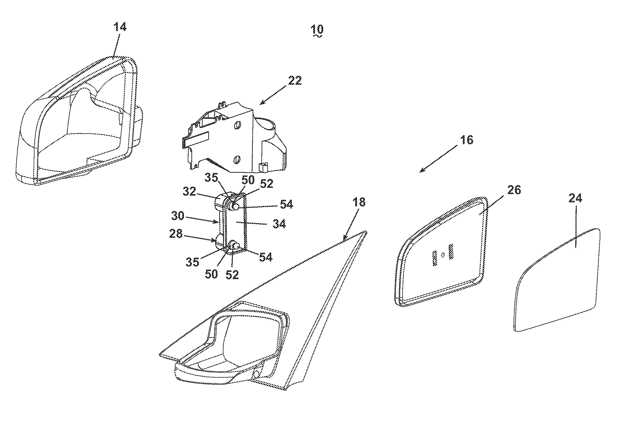
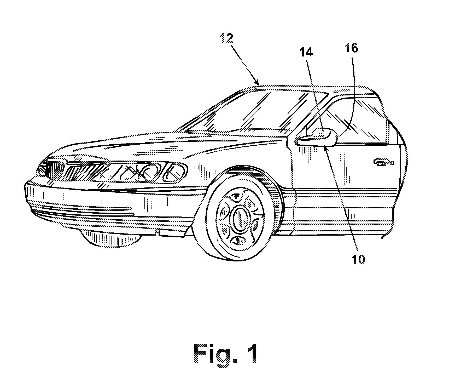
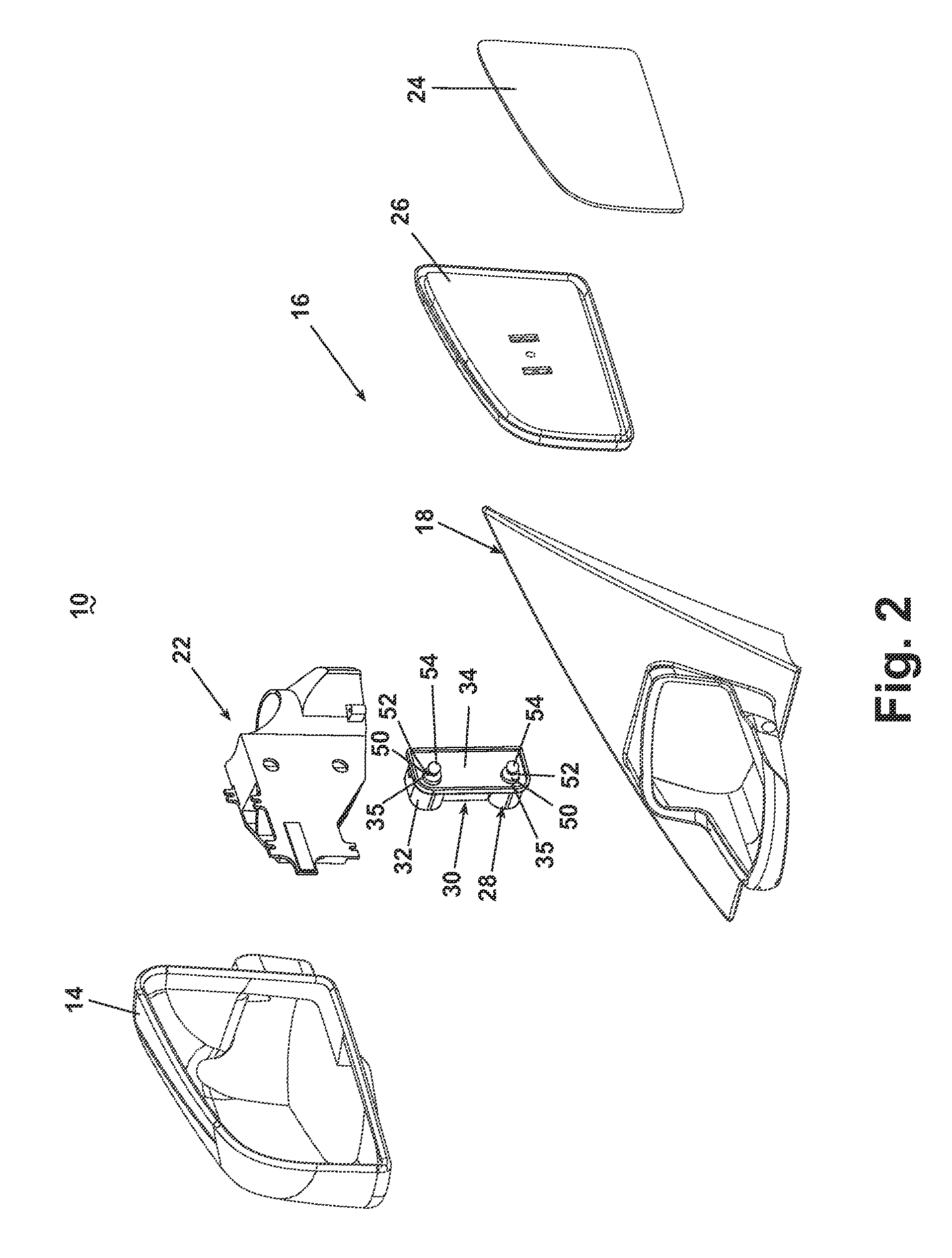
[0036]As illustrated in FIG. 1, an embodiment of a rearview mirror system 10 according to the invention is installed on an automotive vehicle 12 on or near the front of the driver's side door. An identical mirror system can be similarly mounted to the vehicle 12 on the passenger's side. The description of the structure and operation of the mirror system presented hereinafter will be equally applicable to both mirror systems. Although the invention is described herein with respect to one or more exemplary embodiments, the exemplary embodiments of the inventive concepts described herein are not to be considered as limiting, except where the claims expressly state otherwise.

[0037]The rearview mirror system described herein comprises several embodiments of an actuator assembly for tilting a reflective element. The actuator assembly comprises one or more jackscrews which operate within a preselected linear range of travel to tilt the reflective element. Unrestricted operation of the actu...


PUM


Abstract

A motorized tilt actuator assembly comprises one or more threaded jack screws attached to a mirror glass case and traveling along one or more threaded actuator shafts with rotation of the motor. When a jack screw reaches its limit of travel, relative movement between the actuator shaft and the glass case can occur through a slip clutch mechanism during such time as the motor continues to operate. In one embodiment, the relative movement is accommodated by a spherical actuator head rotating in a compressively spring-biased socket. In another embodiment, the relative movement is accommodated by slippage along a friction surface interposed between the actuator shaft and the motor. Manual repositioning of the mirror can be accommodated by slippage of the jack screw threads past the actuator shaft threads, or by a coarse threaded interconnection of the jack screw and the actuator shaft.

Description

CROSS REFERENCE TO RELATED APPLICATIONS[0001]This application claims the benefit of U.S. provisional application Ser. No. 60 / 319,823, filed Dec. 30, 2002, which is incorporated herein in its entirety.BACKGROUND OF INVENTION[0002]1. Field of the Invention[0003]The invention relates to mirrors for automotive vehicles. In one aspect, the invention relates to an improved assembly for mounting a mirror actuator jack screw to a mirror carrier for controlling the vertical and horizontal tilt of the mirror. In one embodiment, the invention relates to a slip clutch applied between each jack screw and the mirror carrier to allow slip between these components when the mirror has reached the end of travel but a drive motor continues to run.[0004]2. Description of the Related Art[0005]Rearview mirrors are standard equipment on automotive vehicles. Frequently, the rearview mirrors can be adjusted by the operator from inside the vehicle through a motorized tilt adjustment mechanism, or tilt actuat...

Claims


Application Information

Patent Timeline
IPC IPC(8): G02B5/08B60R1/06G02B7/182B60R1/072
CPCB60R1/072
Inventor BODDY, IANFOOTE, KEITH D.
Owner MAGNA MIRRORS OF AMERICA
Learn More