
Vacuum pump

Pending Publication Date: 2022-03-17
EDWARDS JAPAN
View PDF0 Cites 0 Cited by
  • Summary
  • Abstract
  • Description
  • Claims
  • Application Information

AI Technical Summary

Benefits of technology

The present invention is designed to prevent damage to a vacuum pump by preventing overheating of its rotating body, and to continuously exhaust a large amount of gas. This improves the production efficiency of semiconductor and flat panel manufacturing devices, reducing waiting time and increasing output.

Problems solved by technology

Unfortunately, the radiant heat transfer described in Japanese Patent Application Laid-Open No. 2005-320905 and the heat dissipation through the gas described in Japanese Patent Application Laid-Open No. 2003-184785 are not enough to ensure a sufficient radiation amount.
For this reason, in the prior art, the flow rate of the gas exhausted by the pump needs to be limited in order to prevent damage resulting from overheating of the rotating body, which makes it difficult to put the primary capacity of the pump to full use.
Particularly in recent years, in order to prevent the accumulation of reaction products in the pump as described above, pumps are configured such that the peripheral parts functioning as the flow paths are kept warm, which makes it more and more difficult to dissipate the heat from the rotating body to the peripheral parts.

Method used


Image

  • Vacuum pump
  • Vacuum pump
  • Vacuum pump

Examples


Embodiment Construction

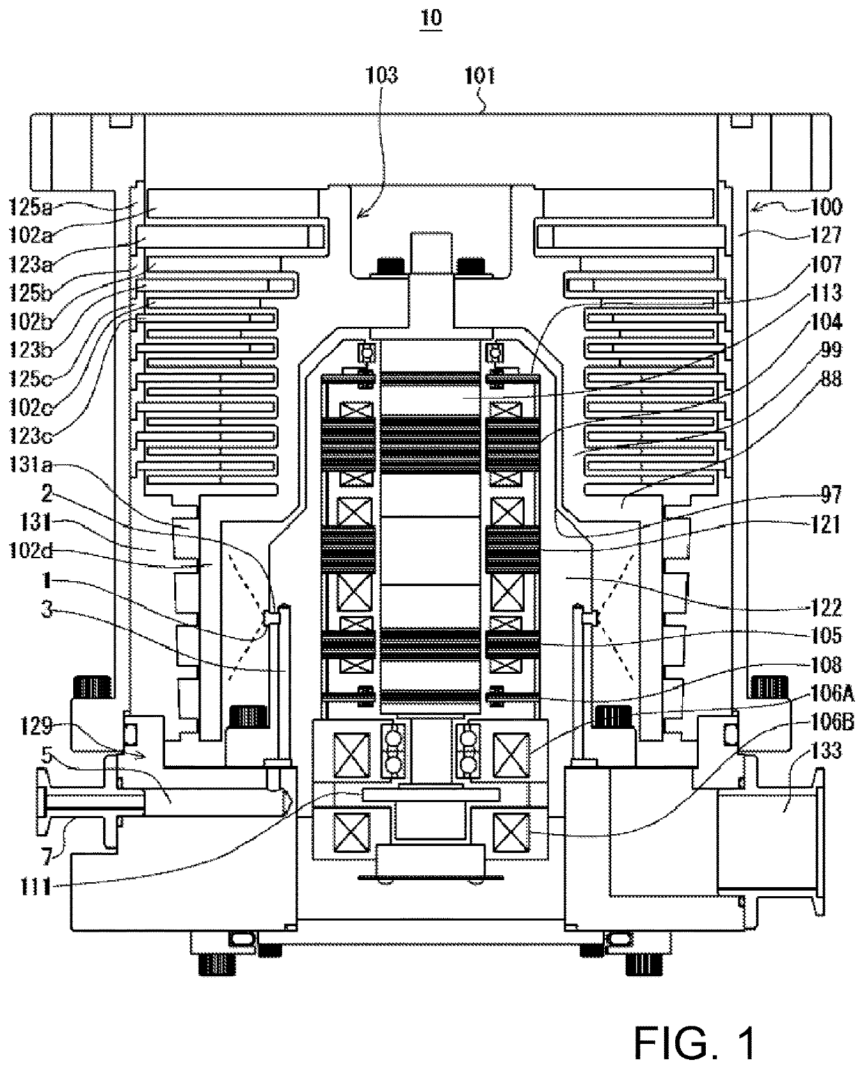
[0049]Embodiments of the present invention are described hereinafter. FIG. 1 shows a configuration diagram of a turbomolecular pump, an embodiment of the present invention.

[0050]In FIG. 1, an inlet port 101 is formed at an upper end of a cylindrical outer cylinder 127 of a pump body 100 of a turbomolecular pump 10. A rotating body 103 in which a plurality of rotor blades 102a, 102b, 102c, etc. are formed radially in multiple stages on a peripheral portion of a hub 99 is provided inside the outer cylinder 127, the rotor blades being configured as turbine blades for drawing and exhausting a gas.

[0051]A rotor shaft 113 is attached to the center of the rotating body 103. The rotor shaft 113 is supported in a levitated manner in the air and has the position thereof controlled by, for example, a so-called 5-axis control magnetic bearing.

[0052]Upper radial electromagnets 104 are four electromagnets arranged in pairs along an X-axis and a Y-axis that are radial coordinate axes of the rotor ...


PUM


Abstract

Decane (C10H22) is sprayed as a mist from spray nozzles toward a rotor blade via a supply pipe and communication passages. Since decane has a boiling point of 174° C. at atmospheric pressure, the decane is a liquid at normal temperature and normal pressure. On the other hand, the pressure inside a turbomolecular pump is in a substantially vacuum state of about 100 Pa, and the boiling point of decane at this pressure is 14° C. Thus, although the pressure is high and the decane is in a liquid state until the decane is sprayed, when the decane adheres to surfaces of the rotor blades and the temperature of the decane rises, the decane vaporizes. At this moment, since the amount of heat of the rotor blades is consumed as heat of vaporization, the rotor blades can be cooled.

Description

CROSS-REFERENCE OF RELATED APPLICATION[0001]This application is a Section 371 National Stage Application of International Application No. PCT / JP2019 / 050887, filed Dec. 25, 2019, which is incorporated by reference in its entirety and published as WO 2020 / 145150A1 on Jul. 16, 2020 and which claims priority of Japanese Application No. 2019-002971, filed Jan. 10, 2019.BACKGROUND OF THE INVENTION[0002]The present invention relates to a vacuum pump, and particularly to a vacuum pump capable of not only preventing damage to a rotating body thereof by preventing overheating of the rotating body, but also exhausting a large amount of gas continuously.[0003]With the recent development of electronics, the demand for semiconductors such as memories and integrated circuits has been increasing rapidly.[0004]These semiconductors are each manufactured by doping an extremely pure semiconductor substrate with impurities to give electrical properties to the semiconductor substrate or by etching a fine...

Claims


Application Information

Patent Timeline
IPC IPC(8): F04D19/04F04D29/58
CPCF04D19/042F05D2210/12F04D29/5846F04D29/5826F04D19/04F04D29/584F04D19/044F04D19/048
Inventor KABASAWA, TAKASHI
Owner EDWARDS JAPAN
Learn More