

Device for axially retaining blades on a turbomachine rotor disk
a technology of axial retaining blades and turbomachines, which is applied in the direction of liquid fuel engines, vessel construction, marine propulsion, etc., can solve the problems of long assembly time, complicated assembly, and use of special tools
- Summary
- Abstract
- Description
- Claims
- Application Information
AI Technical Summary
Benefits of technology
Problems solved by technology
Method used
Image

Examples
Embodiment Construction
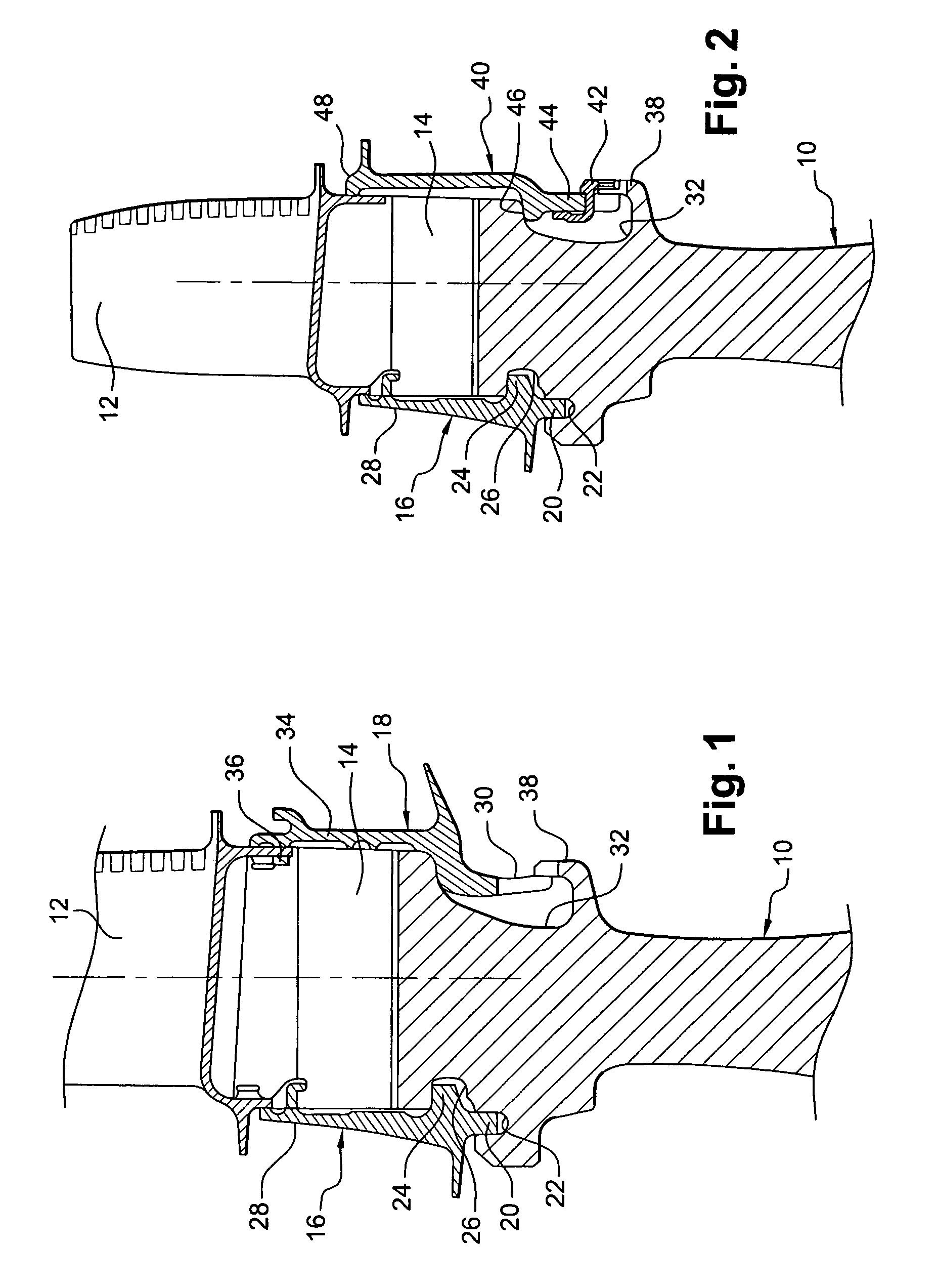
[0032]Reference is made initially to FIG. 1, showing the art prior to the present invention.
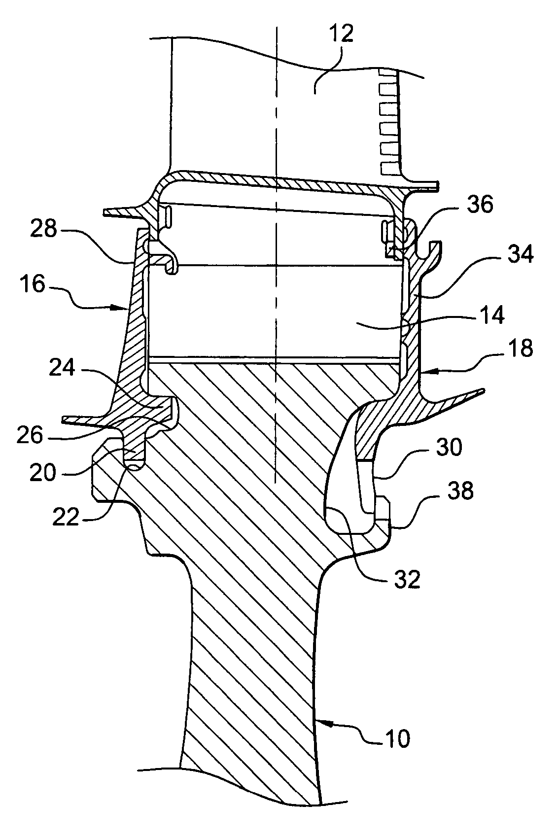
[0033]The rotor of a compressor or a high-pressure turbine of a turbomachine comprises a plurality of rotor disks, one of which is shown in part in FIG. 1, each disk 10 carrying a plurality of substantially radial blades 12 having roots 14 engaged in axial grooves, e.g. of dovetail shape, in the periphery of the disk 10.
[0034]The blades 12 mounted on the disk 10 are prevented from moving axially in the grooves by an upstream annulus 16 and a downstream annulus 18 mounted on the disk.
[0035]On its radially inner portion, the upstream annulus 16 has an inner annular rim 20 facing radially inwards and housed in an annular groove 22 of the upstream face of the disk 10, and a cylindrical rim 24 facing downstream and inserted in a cylindrical groove 26 in the upstream face of the disk 10. The radially outer portion 28 of the upstream annulus 16 bears against the upstream ends of the roots 14 of the ...
PUM
 Abstract
Description
Claims
Application Information