Rotor for laboratory centrifuges

a technology for laboratory centrifuges and rotors, which is applied in the direction of centrifuges, etc., can solve problems such as the risk of damage to the rotor, and achieve the effect of increasing the stiffening effect of the adapter and high rotation speed

Active Publication Date: 2008-05-13
THERMO ELECTRONICS LED GMBH
View PDF25 Cites 6 Cited by
  • Summary
  • Abstract
  • Description
  • Claims
  • Application Information

AI Technical Summary

Benefits of technology

[0025]In another embodiment, the adapter is provided eccentrically to its centerline with a recess into which a sample container can be inserted. The adapter is arranged in the rotor in such a way that the middle distance from the centerline of the sample container to the inner side of the outer wall is smaller than the middle distance from the centerline of the sample container to the inner side of the inner wall. Thus in comparison with the situation in which the centerline of the sample container corresponds with the centerline of the adapter, a greater distance from the sample container to th

Problems solved by technology

Furthermore, the reinforcement of the spoke effect of the ce

Method used


Image

  • Rotor for laboratory centrifuges
  • Rotor for laboratory centrifuges
  • Rotor for laboratory centrifuges

Examples


Embodiment Construction

[0038]Like reference numerals are used for like parts in the figures.

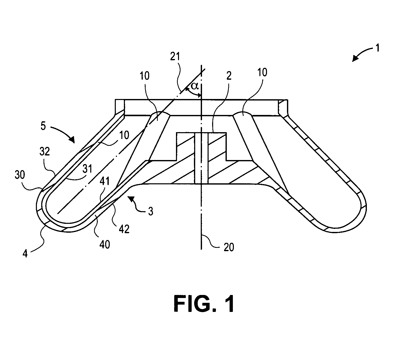
[0039]FIG. 1 illustrates the longitudinal section of a monolithic rotor housing 1 whose rotor hub 2 is arranged centrically in the middle part of an upwardly tapering truncated cone 3 that together with the rotor hub 2 forms the middle region of the rotor housing. The truncated cone 3 is a part of a ring trough 4 and forms a large part of its inner wall 40. Furthermore, the ring trough has an upwardly tapering hollow truncated cone 5 on the side opposite to the truncated cone 3, wherein the truncated cone 5 forms the outer wall 30 of the rotor housing 1. The ring trough 1 has in inner side of the inner wall 41 and an inner side of the outer wall 31 and also an outer side of the inner wall 42 and an outer side of the outer wall 32. The outer peripheral region is formed by the ring trough 4. The rotor rotation axis 20 extends centrally through the rotor hub 2 wherein the centerline 21 of the ring trough 4 forms an an...


PUM


Abstract

The present invention relates to a rotor for laboratory centrifuges, the rotor including a rotor housing that is open to the top and at least one recess for taking up centrifuge containers, with the recess being formed in the peripheral area of the rotor as a concentric, circumferential ring trough having an inner wall and an outer wall and with the ring trough being stiffened in a spoke-type manner in such a way using centrifuge containers that are distributed radially and over the circumference of the ring trough that the centrifuge containers support the inner wall and the outer wall rigidly against one another. Furthermore, an adapter for receiving a sample container and for use in such a rotor is suggested.

Description

BACKGROUND OF THE INVENTION[0001]1. Field of the Invention[0002]The present invention relates to a rotor for laboratory centrifuges wherein said rotor comprises a rotor housing that is open to the top and has at least one recess for taking up centrifuge containers, wherein the recess is formed in the peripheral area of the rotor as a concentric circumferential ring trough with an inner wall and an outer wall and also an adapter for taking up a sample container and for use in such a laboratory centrifuge rotor.[0003]2. Description of the Related Art[0004]In this context, a centrifuge container can firstly be a sample container in which the samples to be centrifuged are arranged. Secondly, a centrifuge container can also be an adapter that can be inserted into a rotor and into which a sample container can in turn be inserted.[0005]A rotor for a laboratory centrifuge is used in order to take up centrifuge containers in which material to be centrifuged is contained. A centrifuge contain...

Claims


Application Information

Patent Timeline
IPC IPC(8): B04B5/02
CPCB04B5/0414B04B7/08B04B2005/0435B04B7/085
Inventor EIGEMEIER, FRANKKROLL, SUSANNEGROTHAUS, RAIMUND
Owner THERMO ELECTRONICS LED GMBH
Why Eureka
Try Eureka