Check patentability & draft patents in minutes with Patsnap Eureka AI!

Method of manufacturing magnetic head

a manufacturing method and magnetic head technology, applied in the direction of maintaining the head carrier alignment, photomechanical equipment, instruments, etc., can solve the problems of the difficulty of accurately attaching the suspension by taking the external shape of the slider as a reference, and the inability to achieve the design flying attitude and electrical characteristics. , to achieve the effect of reducing the height of the flying vehicle, reducing the difficulty of manufacturing, and reducing the cost of production

Active Publication Date: 2008-05-13
SAE MAGNETICS H K LTD 50
View PDF7 Cites 0 Cited by
  • Summary
  • Abstract
  • Description
  • Claims
  • Application Information

AI Technical Summary

Benefits of technology

This approach enables stable flying attitude and electrical characteristics by maintaining a balance between positive and negative pressures, improving attachment precision and reliability, even in miniaturized designs with complex patterns.

Problems solved by technology

However, problems like those described below exist with the conventional magnetic head manufacturing methods described above.
The designed flying attitude and electrical characteristics may thus not be obtainable.
Accompanying miniaturization of sliders and more complex ABS patterns (in order to stabilize flying characteristics), it is expected that accurately attaching the suspension by taking the external shape of the slider as a reference will become increasingly difficult.
Furthermore, there is a fear that a balance between positive pressure and negative pressure in the ABS will go out of balance, making it impossible to stabilize the flying attitude of the slider, when forming through holes and the like used for positioning in the slider itself.

Method used


Image

  • Method of manufacturing magnetic head
  • Method of manufacturing magnetic head
  • Method of manufacturing magnetic head

Examples


Embodiment Construction

[0027]Specific preferred embodiments of a method of manufacturing a magnetic head according to the present invention are explained in detail below while referring to the appended drawings.

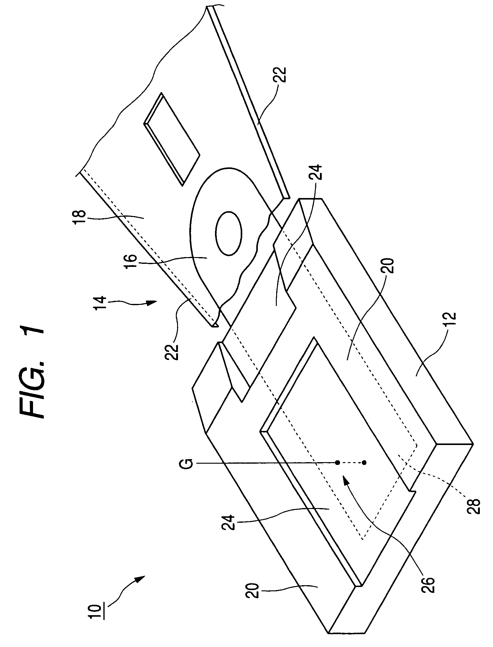
[0028]FIG. 1 is a perspective view of a magnetic head that is manufactured by using a method of manufacturing a magnetic head according to this embodiment. Referring to FIG. 1, a magnetic head 10 that is manufactured by using the method of manufacturing a magnetic head according to this embodiment includes a slider 12 in which giant magneto-resistive (GMR) element is incorporated, and a suspension 14 that is fixed to the slider 12. The suspension 14 includes a flexure 16 that is bonded and fixed to the slider 12, a load beam 18 that is connected to the flexure 16 by spot welding, and a flexible printed circuit (FPC)(not shown) that provides wirings for the GMP element that is formed on the slider 12.

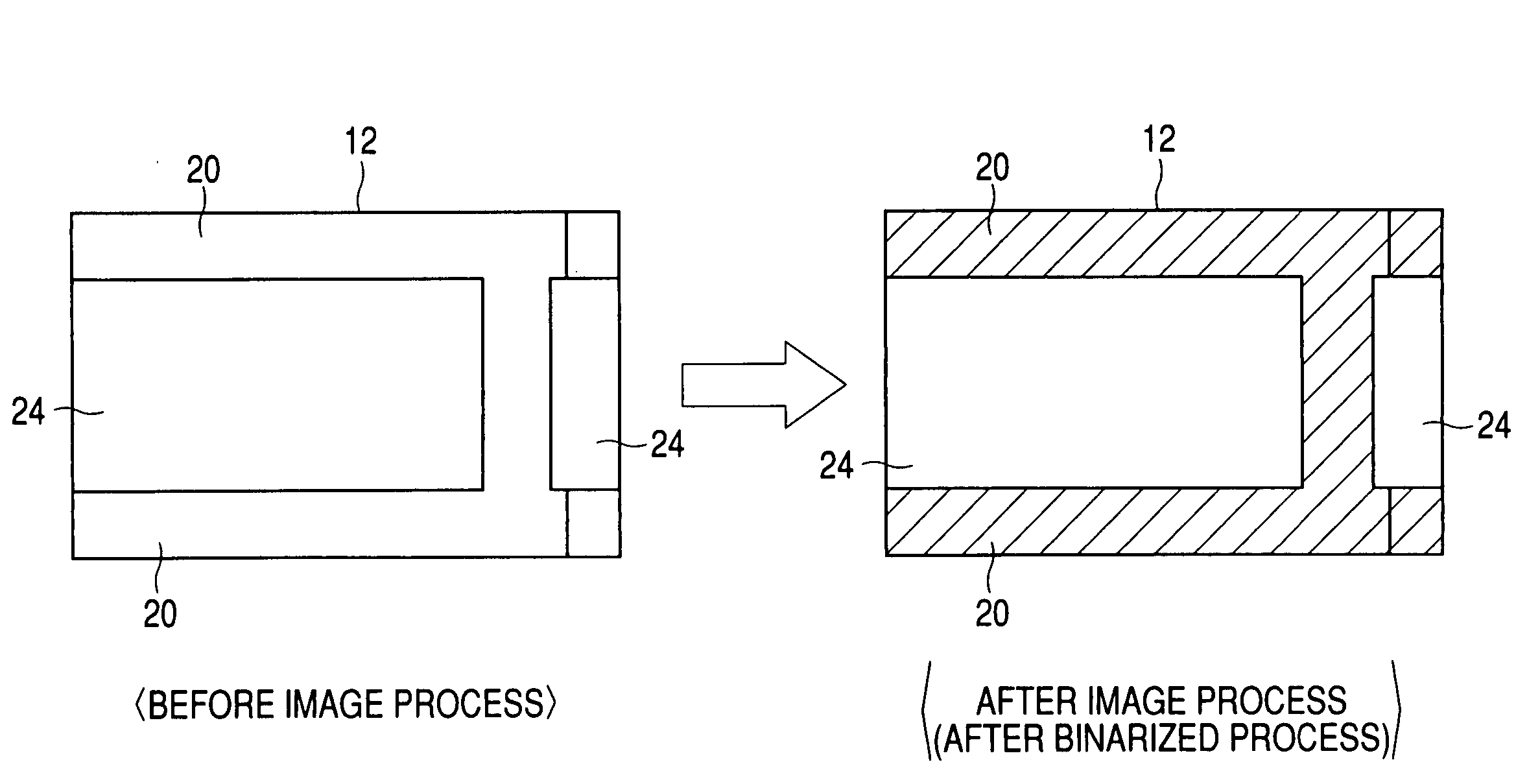
[0029]An ABS is formed on a side of the slider 12 opposed to a magnetic disk (not shown) that is fix...


PUM

PropertyMeasurementUnit
wavelengthaaaaaaaaaa
shapeaaaaaaaaaa
electrical characteristicsaaaaaaaaaa

Abstract

Provided is a method of manufacturing a magnetic head with which bonding of a slider and a suspension can be performed by taking an ABS pattern, which determines flying characteristics, as a reference, with no special fabrication required on the slider or the suspension. The method relates to a method of manufacturing a magnetic head for attaching a slider, on which an air bearing surface (ABS) is formed, to a suspension. A surface of the slider on which the ABS is formed is photographed, and the ABS and an engraved region formed within the ABS are identified from the photographed image. Then, a reference that serves as a guide in attaching the suspension is computed, and the slider is attached to the suspension based on the reference. It thus becomes possible for positive pressure and negative pressure that occur in the ABS to be well balanced centered about the suspension, making it possible to stabilize flying attitude and electrical characteristics.

Description

BACKGROUND OF THE INVENTION[0001]1. Field of the Invention[0002]The present invention relates to a method of manufacturing a magnetic head. In particular, the present invention relates to a method of manufacturing a magnetic head suitable for attaching a slider to a suspension with good accuracy.[0003]2. Related Background Art[0004]Hard disk drives (hereinafter called HDDs) are increasing in capacity and being made thinner. Together with these advances, magnetic heads (20%, 30% sliders) are also being made smaller.[0005]When bonding a slider, on which a giant magneto-resistive (GMR) element is formed, to a suspension side with conventional processes of manufacturing magnetic heads, positioning of the slider is performed first using the external shape of the slider as a reference. An adhesive agent is applied to a rear surface side of the slider (side opposite to a side where an air bearing surface (ABS) is formed) after positioning the slider, and the slider side is made to contact ...

Claims


Application Information

Patent Timeline
Patent Type & Authority Patents(United States)
IPC IPC(8): G11B21/21G11B5/60G11B5/48
CPCG11B5/4826G11B5/6005Y10T29/49027Y10T29/49037Y10T29/4903G11B5/3169G11B5/455
Inventor TAKANUKI, KAZUAKISHINDO, OSAMUNAKAO, AKIMASAKANEKO, MASAAKIYAMAGUCHI, SATOSHI
Owner SAE MAGNETICS H K LTD 50
Features
  • R&D
  • Intellectual Property
  • Life Sciences
  • Materials
  • Tech Scout
  • Unparalleled Data Quality
  • Higher Quality Content
  • 60% Fewer Hallucinations
Learn More