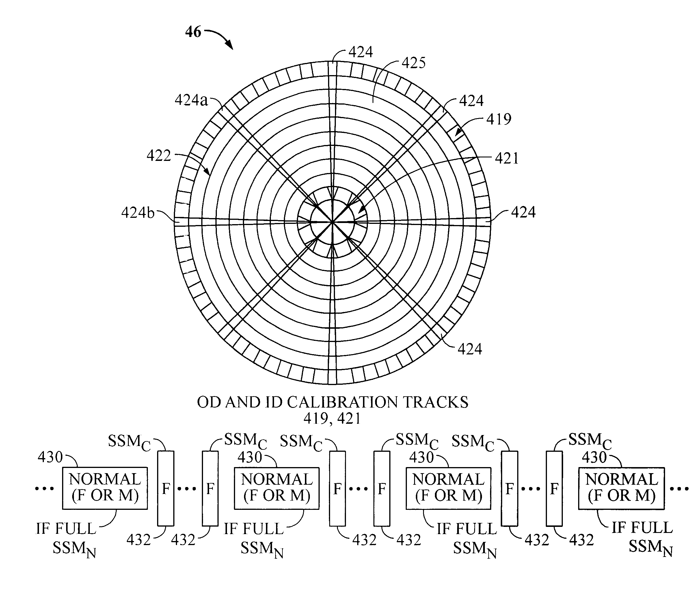
Rotating media storage device having a calibration track with unique calibration servo synch marks
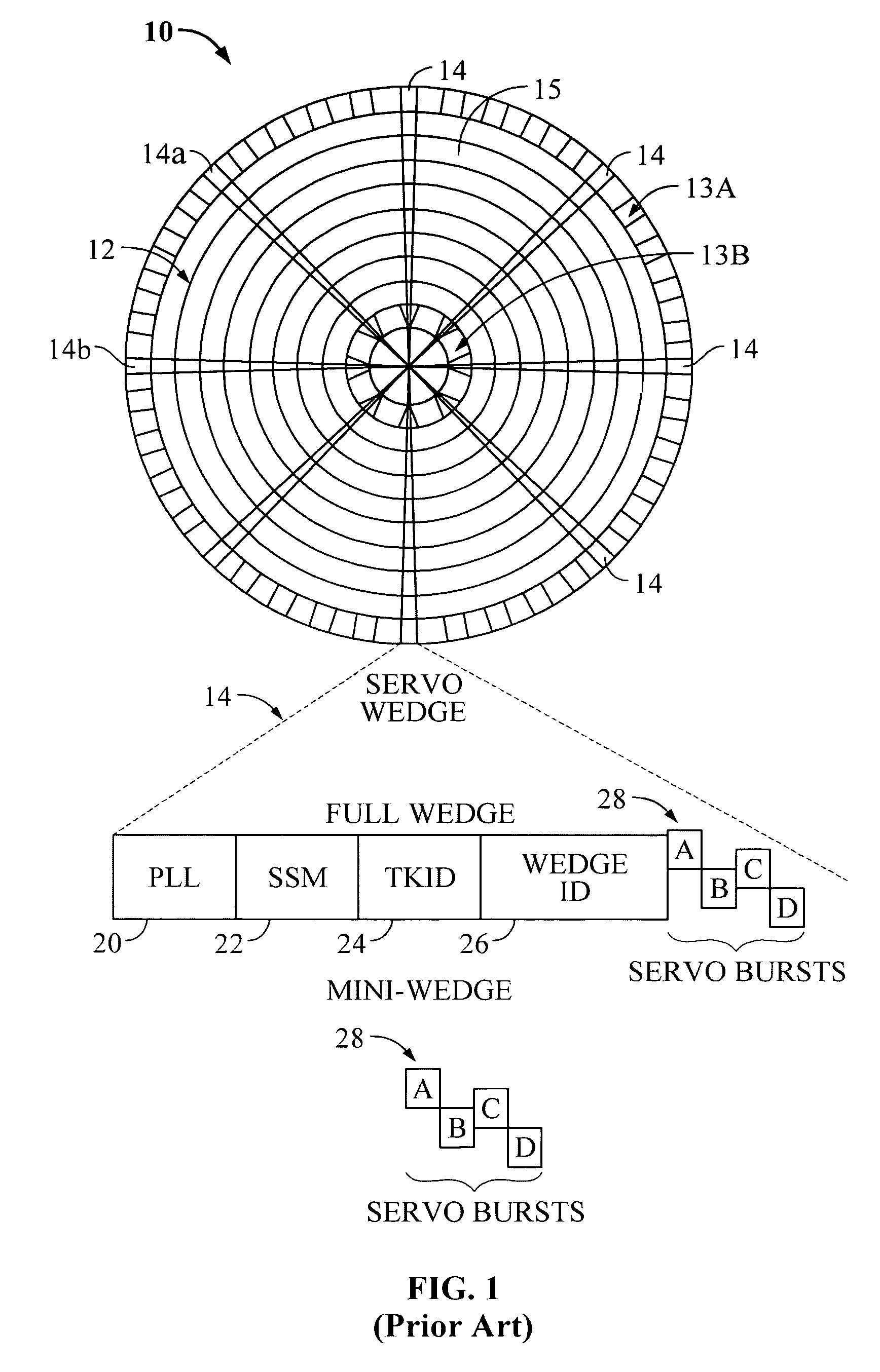
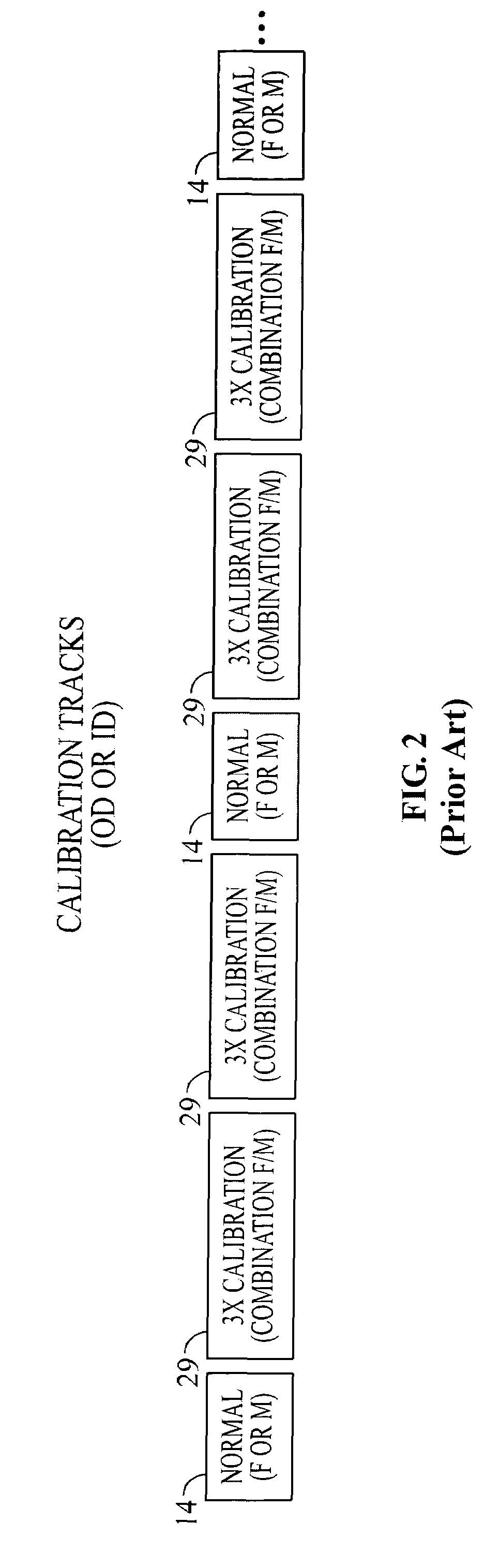
a technology of rotating media storage and calibration track, which is applied in the direction of magnetic recording, data recording, instruments, etc., can solve the problems of disk drive failure, high computational intensity of servo control, and the inability to utilize servo control to track along the mini-wedges
- Summary
- Abstract
- Description
- Claims
- Application Information
AI Technical Summary
Benefits of technology
Problems solved by technology
Method used
Image

Examples
Embodiment Construction
[0032]In the following description, the various embodiments of the invention will be described in detail. However, such details are included to facilitate understanding of the invention and to describe exemplary embodiments for employing the invention. Such details should not be used to limit the invention to the particular embodiments described because other variations and embodiments are possible while staying within the scope of the invention. Furthermore, although numerous details are set forth in order to provide a thorough understanding of the embodiments of the invention, it will be apparent to one skilled in the art that these specific details are not required in order to practice the embodiments of the invention. In other instances details such as, well-known methods, types of data, protocols, procedures, components, electrical structures and circuits, are not described in detail, or are shown in block diagram form, in order not to obscure the invention. Moreover, embodimen...
PUM
| Property | Measurement | Unit |
|---|---|---|
| outer diameter | aaaaa | aaaaa |
| inner diameter | aaaaa | aaaaa |
| time | aaaaa | aaaaa |
Abstract
Description
Claims
Application Information
 - Generate Ideas
- Intellectual Property
- Life Sciences
- Materials
- Tech Scout
- Unparalleled Data Quality
- Higher Quality Content
- 60% Fewer Hallucinations
Browse by: Latest US Patents, China's latest patents, Technical Efficacy Thesaurus, Application Domain, Technology Topic, Popular Technical Reports.
© 2025 PatSnap. All rights reserved.Legal|Privacy policy|Modern Slavery Act Transparency Statement|Sitemap|About US| Contact US: help@patsnap.com