
Apparatus and method for channel encoding/decoding in a communication system

a communication system and apparatus technology, applied in the field of communication systems, can solve the problems of increasing the amount of calculations, and transmission time, and increasing the power consumption of the decoder in a good channel condition,

Inactive Publication Date: 2008-05-13
QUALCOMM INC
View PDF8 Cites 4 Cited by
  • Summary
  • Abstract
  • Description
  • Claims
  • Application Information

AI Technical Summary

Benefits of technology

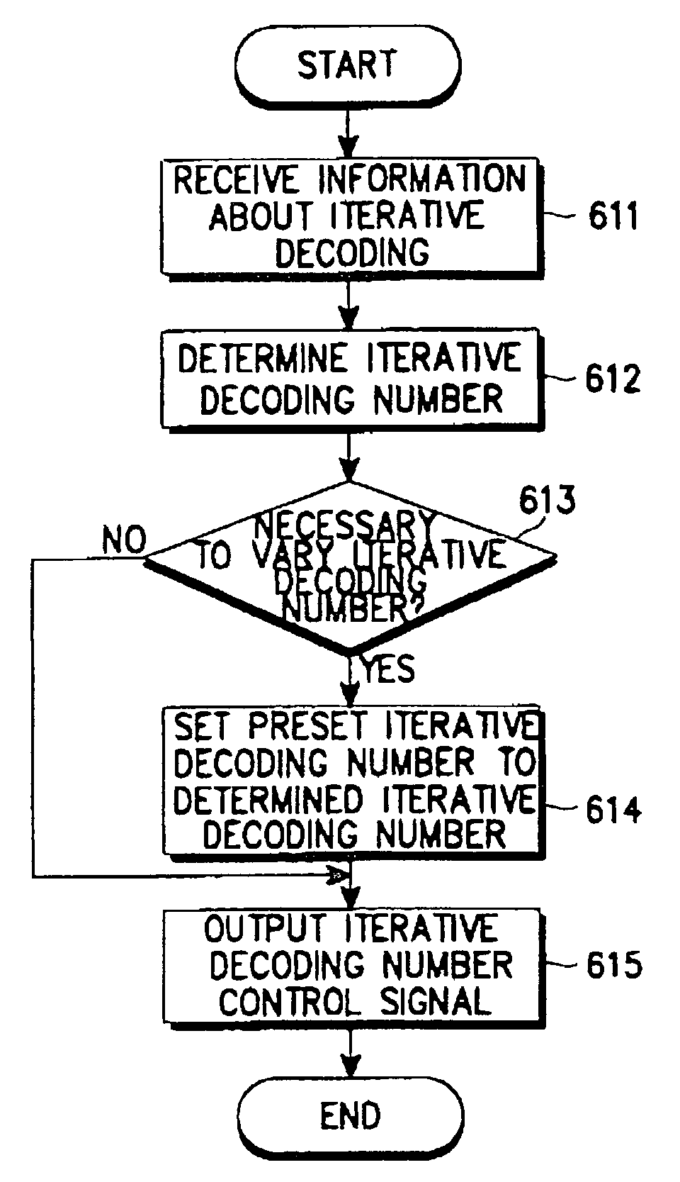
The present invention provides a channel encoding / decoding apparatus and method for varying an iterative decoding number according to a service type and a data class. The apparatus can also determine the iterative decoding number based on the channel condition as a function of time. This allows for efficient and effective decoding of received messages based on their importance and urgency.

Problems solved by technology

However, an increase in the iterative decoding number inevitably leads to an increase in the amount of calculations, power consumed by the decoder, and transmission time.
However, since the condition of a transmission channel varies with time, a desired bit error rate may not be obtained with the fixed iterative decoding number when the condition of the receiving channel is worse as compared to a predetermined condition.
However, when the iterative decoding number is fixed to a maximum value in consideration of only the worst channel condition, the amount of calculations unnecessarily increases, causing an increase in power consumption of the decoder in a good channel condition.

Method used


Image

  • Apparatus and method for channel encoding/decoding in a communication system
  • Apparatus and method for channel encoding/decoding in a communication system
  • Apparatus and method for channel encoding/decoding in a communication system

Examples


first embodiment

[0030]FIG. 4 illustrates a channel receiver including a channel decoder in accordance with a A demodulator 412 demodulates an input signal received via a transmission channel 411. A channel deinterleaver 413 deinterleaves an output of the demodulator 412. A message information receiver 401 receives the message information transmitted from the message information transmitter 301 of FIG. 3, and provides it to a CPU 400. The CPU 400 analyzes the received message information and provides information about iterative decoding to an iterative decoding controller 402. The iterative decoding controller 402 then analyzes the iterative decoding information provided from the CPU 400 to determine the iterative decoding number according to the analysis, and controls the soft-decision decoder 414 according to the determined iterative decoding number. Here, the iterative decoding number is decreased for a moving picture service permitting only a short time delay, and increased for a character serv...

second embodiment

[0034]FIG. 5 illustrates a channel receiver including a channel decoder according to the present invention. Referring to FIG. 5, the channel receiver does not include the message information transmitter 401 of FIG. 4. However, the channel receiver can be separately provided with the message information about the service type and data class from the transmitter.

[0035]In the channel receiver of FIG. 5, a channel condition analyzer 501 varies the iterative decoding number of a soft-decision decoder 514 according to the channel condition over time. The channel condition is compared to a predetermined channel condition and the iterative decoding number is adjusted accordingly. For example, in a CDMA communication system, when a base station exchanges data with multiple mobile stations, the base station provides the respective mobile stations with an interference level signal among reverse channel signals received from the mobile stations on a broadcasting channel. This interference level...


PUM


Abstract

An apparatus and method for channel encoding / decoding are provided which vary an iterative decoding number according to service type, data class and channel condition. A message information receiver receives information about a message to be received. A controller determines an iterative decoding number according to the message information received. A decoder iteratively decodes the received message according to the determined iterative decoding number. The message information includes a class of received data, and the class includes a bit error rate (BER). The iterative decoding number is increased for a low BER as compared to a predetermined BER. Further, the class includes a permissible time delay, and the iterative decoding number is increased for a long permissible time delay as compared to a predetermined permissible time delay. In addition, the message information includes a service type of the received data, and the iterative decoding number is decreased when the service type is a moving picture service.

Description

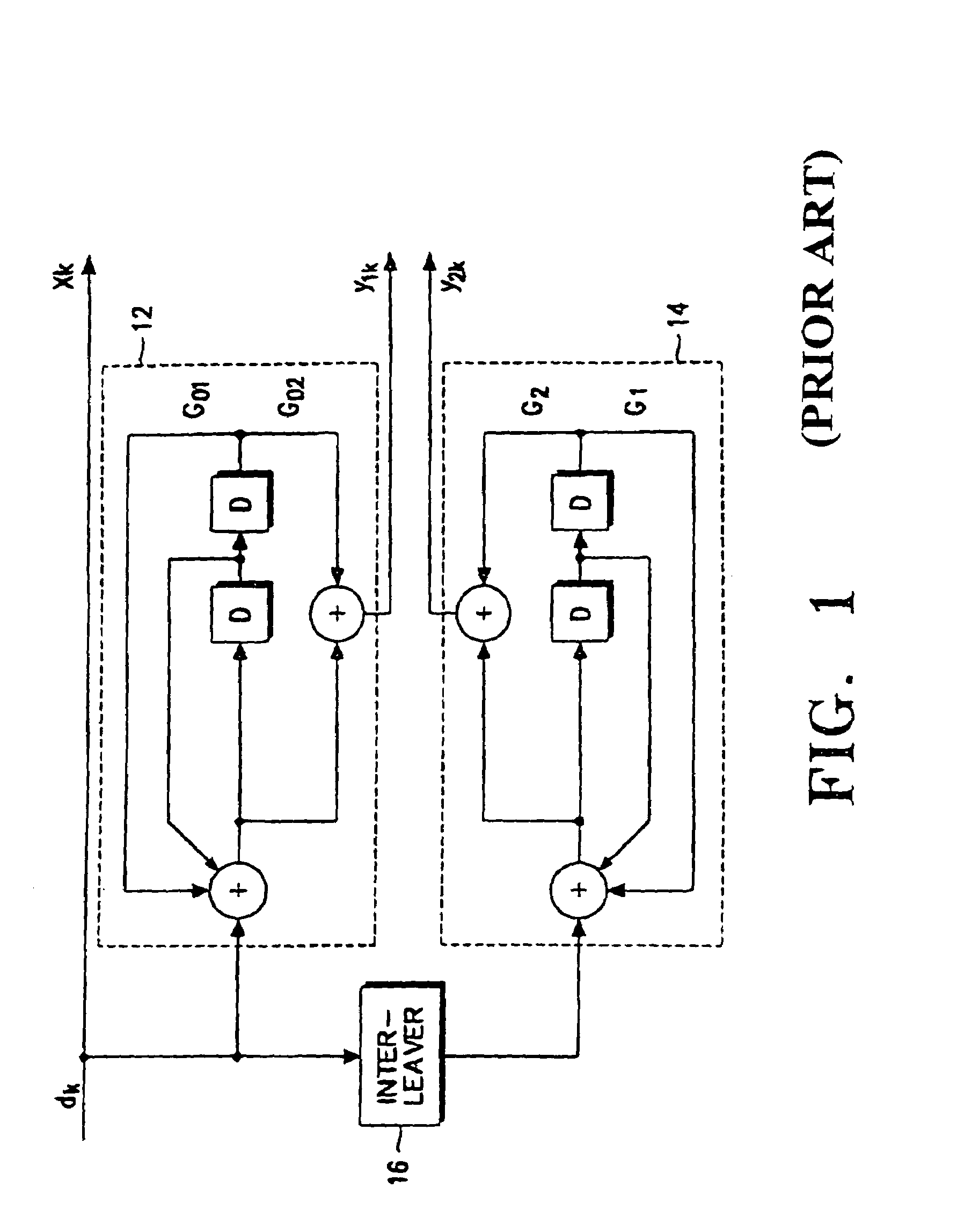
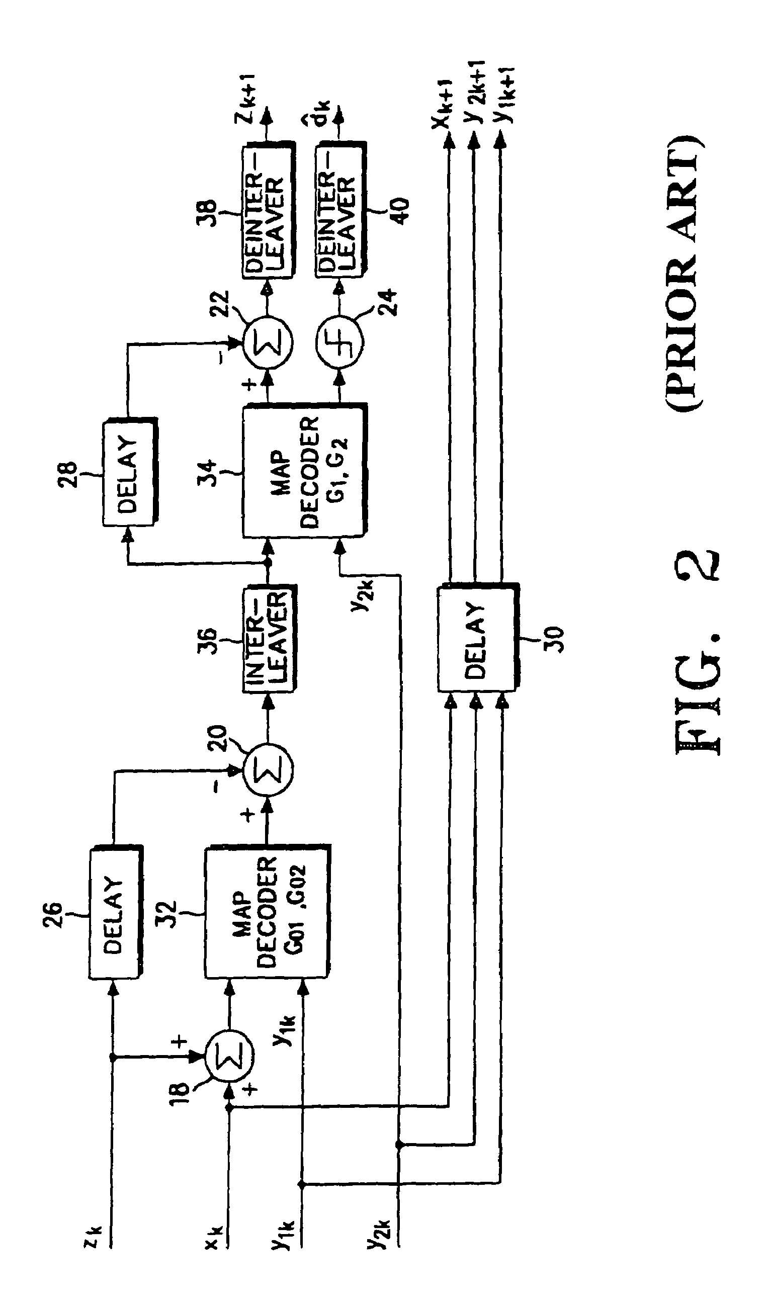
PRIORITY[0001]This application is a Divisional of parent application Ser. No. 09 / 294,659, filed on Apr. 19, 1999 now U.S. Pat. No. 6,885,710.[0002]This application claims priority to an application entitled “Channel Encoding / Decoding Apparatus and Method For Communication System” filed in the Korean Industrial Property Office on Apr. 18, 1998 and assigned Serial No. 98-13957, the contents of which are hereby incorporated by reference.BACKGROUND[0003]1. Field of the Invention[0004]The present invention relates generally to a communication system, and more particularly, to an apparatus and method for channel encoding / decoding for performing soft-decision iterative decoding in a communication system.[0005]2. Description of the Related Art[0006]A turbo encoder is a typical channel encoder which supports iterative decoding. The turbo encoder is classified into a parallel turbo encoder and a serial turbo encoder. Although the present invention will be described with reference to the paral...

Claims


Application Information

Patent Timeline
Patent Type & Authority Patents(United States)
IPC IPC(8): H03D1/00H04L27/06H03M13/00H03M13/41H03M13/13H03M13/29H04B7/15H04L17/30H04L27/00H04L29/00
CPCH03M13/2957H03M13/2975H04L1/0066H03M13/6337H04L1/0051H03M13/3707H04B7/15
Inventor PARK, CHANG-SOOLEE, HYEON-WOO
Owner QUALCOMM INC
Learn More