Texture image compressing device and method, texture image decompressing device and method, data structures and storage medium

a compression device and texture technology, applied in the field of texture image compression device and method, texture image decompression device and method, data structure and storage medium, can solve the problems of complex software, high-performance processor, and difficulty in making such a vector calculation

Inactive Publication Date: 2008-05-13
KK TOSHIBA
View PDF9 Cites 34 Cited by
  • Summary
  • Abstract
  • Description
  • Claims
  • Application Information

AI Technical Summary

Benefits of technology

[0024]Embodiments consistent with the present invention may provide a texture image compressing device that can compress a plurali...

Problems solved by technology

It has been difficult to make such a vector calculation, because a very-high-performance processor and very complex software have been needed.
However, there is a problem even with these improved texture mapping methods.
Because a single texture image is pasted regardless of the 3D position of the polygon, the methods cannot express the optical characteristics of the object surface that change in accordance with the viewpoint direction and the light source direction.
Thus, this method has the problem that there are many calculations required.
However, there has been no example of BTF in which sampling of an image has been conducted while changing all four variables representing the viewpoint direction and the light source direction.
Thus, it is difficult to generate textures in consideration of bo...

Method used


Image

  • Texture image compressing device and method, texture image decompressing device and method, data structures and storage medium
  • Texture image compressing device and method, texture image decompressing device and method, data structures and storage medium
  • Texture image compressing device and method, texture image decompressing device and method, data structures and storage medium

Examples


first embodiment

[0051]A texture image compressing device of a first embodiment consistent with the invention will be described below with reference to the drawings.

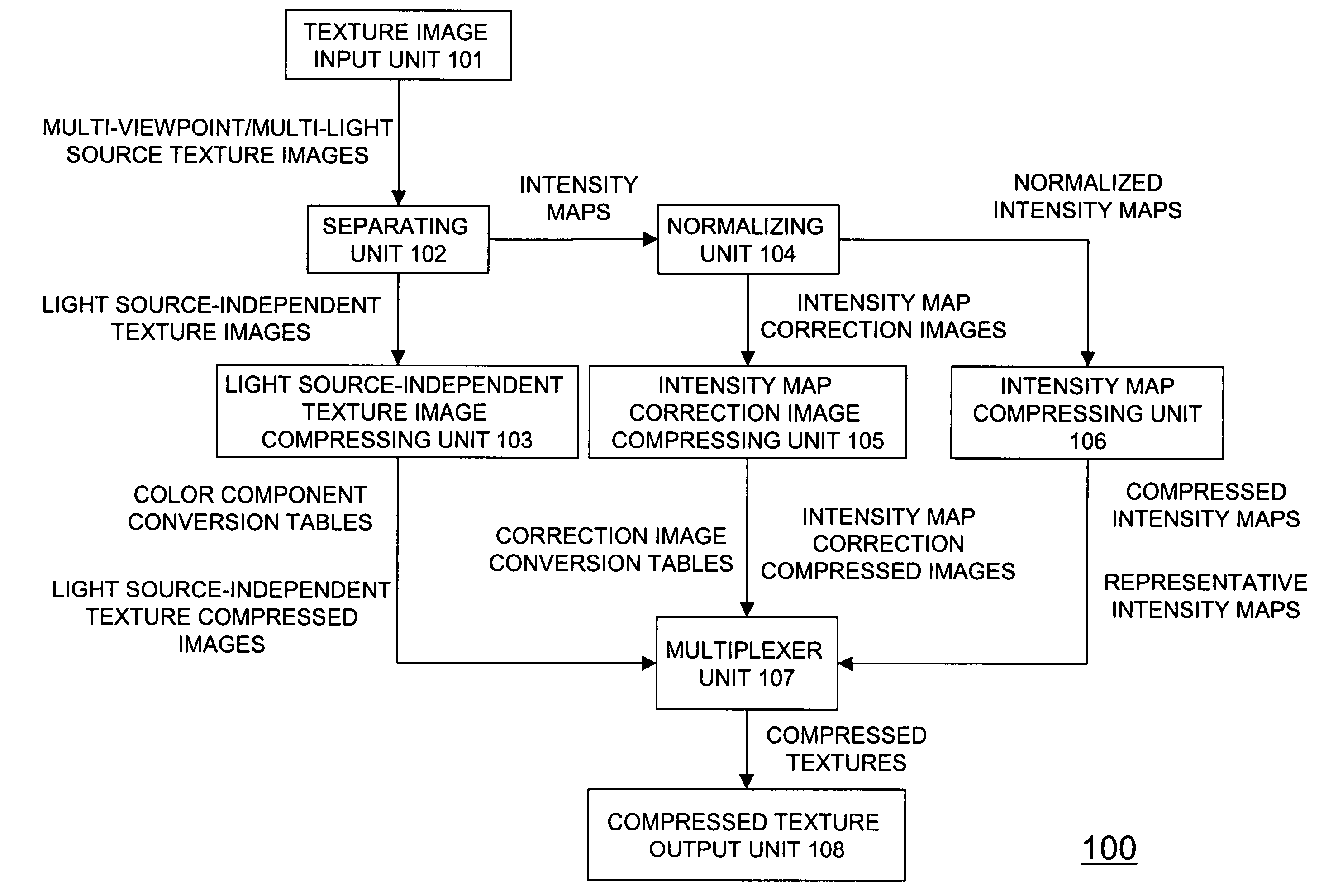
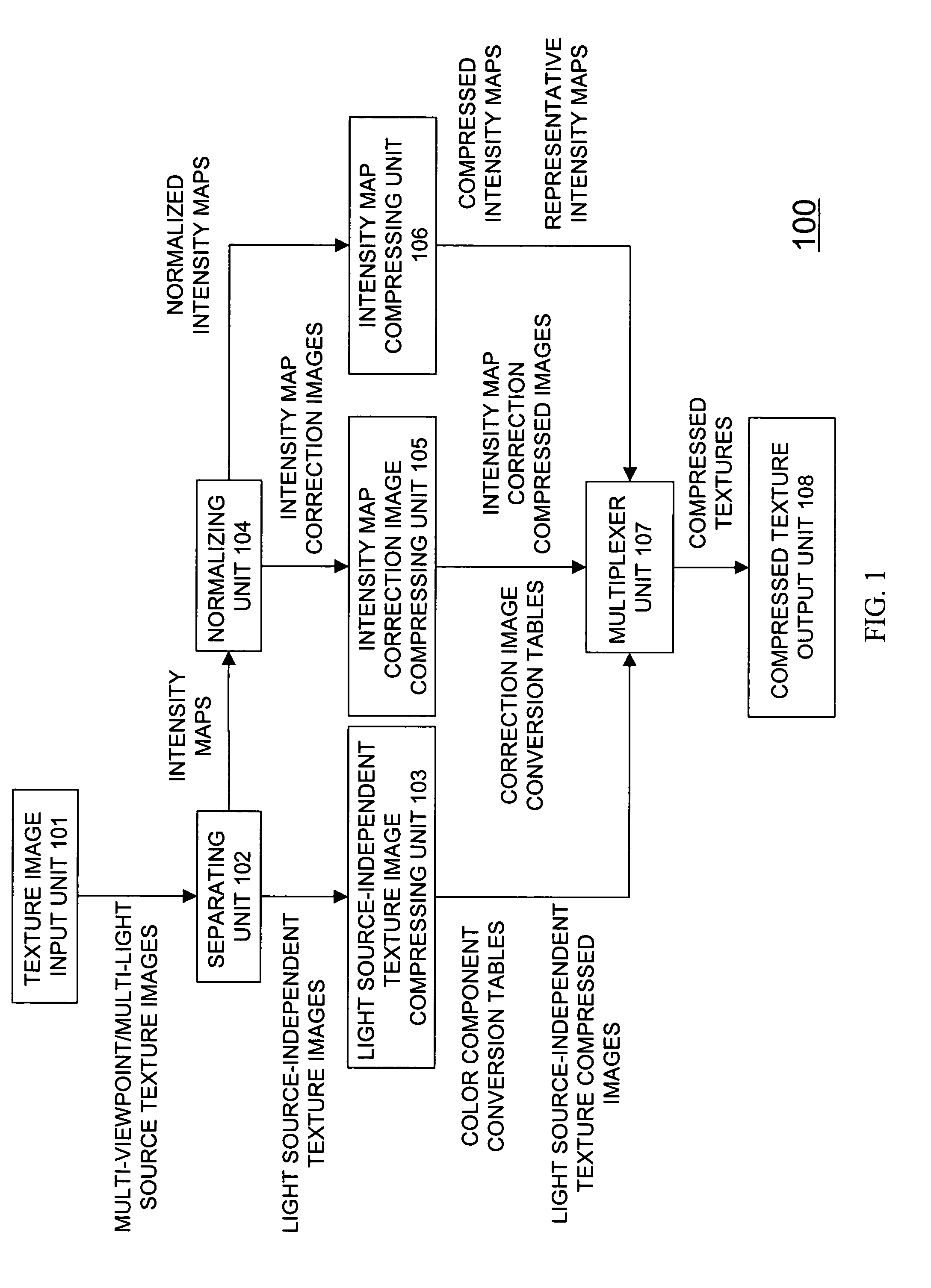
[0052]Texture mapping is a method used in the field of three-dimensional(3D) computer graphics that expresses an object by dividing the object surface into a plurality of polygons and pasting a texture image onto each polygon to generate a two-dimensional image.

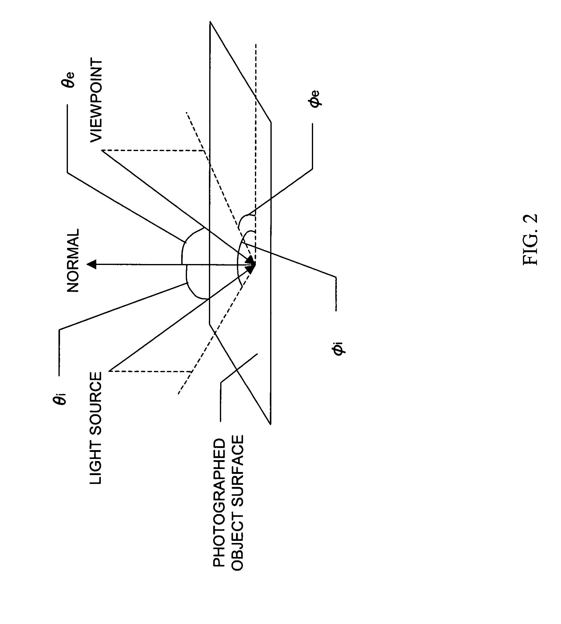
[0053]The 3D object's appearance depends on the viewpoint direction and the light source direction. When either the viewpoint direction or the light source direction changes, the 3D object's appearance changes. A change in the viewpoint direction mainly influences the 3D position of the polygons, i.e., the 3D position of the texture images pasted on each polygon. A change in the light source direction mainly influences the optical characteristics of the polygons, i.e., the optical characteristics such as the intensity distribution of the texture images pasted on each polygon. Thus...

second embodiment

[0200]A second embodiment will be described below with reference to the drawings.

[0201]The second embodiment relates to a texture decompressing device that decompresses texture images of desired viewpoint directions and desired light source directions from the compressed texture generated by the texture compressing device of the first embodiment. The texture decompressing device of the second embodiment decompresses texture images of desired viewpoint directions and desired light source directions from compressed texture 1100 (including the representative intensity maps 1101, the conversion tables 1102 and 1103, and the compressed texture blocks 1104-1 to 1104-N) having the data structure shown in FIG. 11.

[0202]It should be noted that, similar to the texture compressing device of the first embodiment, the texture decompressing device of the second embodiment is also realized as a program operated on a computer. However, part or all of the configuration of the device can also be real...


PUM


Abstract

A texture image compressing device includes a separating unit configured to separate intensity maps, including intensity values and light source-independent texture images, those images including color components from a plurality of texture images corresponding to different light source directions and different viewpoint directions. The device includes an intensity map compressing unit configured to compress the intensity maps to generate compressed intensity maps and representative intensity maps that are codebooks of the compressed intensity maps, a light source-independent texture image compressing unit configured to compress the light source-independent texture images to generate light source-independent texture compressed images and color component conversion tables that are codebooks of the light source-independent texture compressed images, and a compressed texture generating unit configured to generate compressed textures by combining the compressed intensity maps, the representative intensity maps, the light source-independent texture compressed images and the color component conversion tables.

Description

CROSS-REFERENCE TO RELATED APPLICATION[0001]This application is based upon and claims the benefit of priority from prior Japanese Patent Application No. P2002-21423 filed on Jan. 30, 2003, the entire contents of which are incorporated herein by reference.BACKGROUND[0002]1. Field of the Invention[0003]The present invention relates to a texture compressing device and method. The device and method are for compressing texture image data. Texture images are used in realizing optical characteristics of an object surface that change in accordance with viewpoint directions and light source directions in texture mapping.[0004]The present invention also relates to a texture decompressing device and method used in decompressing original texture images from texture image data compressed by the aforementioned texture compressing device or method.[0005]The present invention also relates to data structures of texture images compressed by the aforementioned texture compressing device or method.[000...

Claims


Application Information

Patent Timeline
IPC IPC(8): G06K9/36G06T15/00G06T15/04
CPCG06T9/001G06T15/04G06T15/205
Inventor YAMAUCHI, YASUNOBUYANAGAWA, SHINGOSEKINE, MASAHIRONAGAI, TAKESHIUNEO, HIDEYUKIKOGURE, NAKABA
Owner KK TOSHIBA
Why Eureka
Try Eureka