Support element

a technology of supporting elements and supporting components, which is applied in the direction of liquid fuel feeders, machines/engines, mechanical equipment, etc., can solve the problems of valve needle seizure, change of lift, and various holding components exerting strain on the fuel injector, so as to achieve the effect of flexible support of the fuel distributor, which may be further improved without additional manufacturing costs

Inactive Publication Date: 2008-05-20
ROBERT BOSCH GMBH
View PDF15 Cites 23 Cited by
  • Summary
  • Abstract
  • Description
  • Claims
  • Application Information

AI Technical Summary

Benefits of technology

[0004]In contrast, the support element for a fuel injector according to the present invention has the advantage that the fuel distributor rests against the fuel injector via the support element without any radial force being exerted, which means there is no stress and subsequent damage to the fuel injector or to the fuel distributor connector. Due to an appropriately designed bracket, the fuel injector protruding through a hole therein, and clips, the support element ensures that the hold-down force of the fuel distributor is transferred onto the fuel injector, and also allows fixing to be flexible so that tolerances and offsets are compensated for.
[0006]It is advantageous that the support element may be manufactured in a simple manner by stamping and bending sheet metal. It may also be manufactured via deep-drawing and stamping.
[0009]Furthermore, it is advantageous that, by providing a further elastic bracket which is symmetrical to the first bracket, the flexible support of the fuel distributor may be further improved without additional manufacturing cost.

Problems solved by technology

The disadvantage of the known attachment device disclosed in DE 29 26 490 is in particular the fact that the various holding components exert strain upon the fuel injector.
The flux of force generated in the fuel injector results in deformations and thereby in changes in the lift and even seizure of the valve needle, and also results in pressure load or bending load on the housing components, which as a general rule have thin walls and are welded to one another at various points.
Moreover, every attachment means, e.g., a contact collar, increases the radial dimension of the fuel injector, which in turn means more space is required for installation.

Method used


Image

  • Support element
  • Support element
  • Support element

Examples


Embodiment Construction

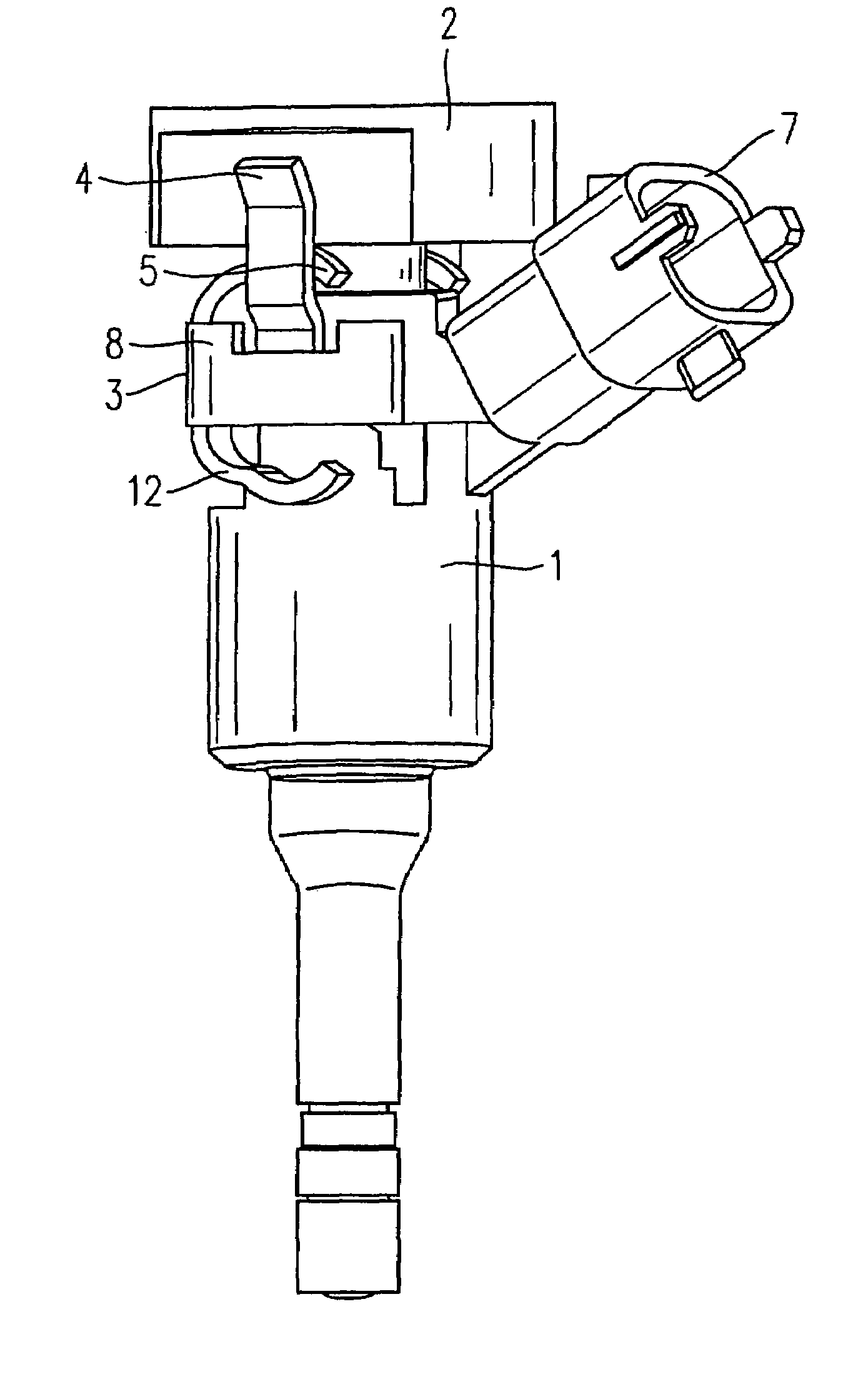
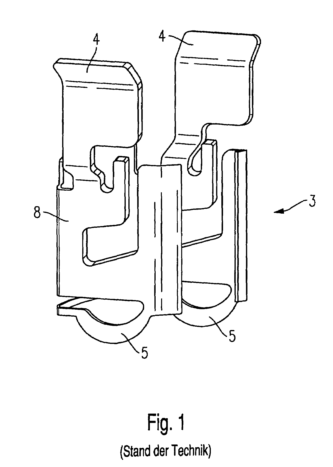
[0017]To explain the measures according to the present invention, FIG. 1 first shows a schematic view of a related-art support element 3. Support element 3 is used to secure a fuel injector (not shown in FIG. 1) in a cylinder head of an internal combustion engine and to connect the fuel injector to a fuel distributor. The fuel injector is for example designed as a high-pressure injector of a mixture-compressing, spark-ignition internal combustion engine.

[0018]To maintain clearance between the fuel injector and the fuel distributor without radial force being exerted, support element 3 must have elasticity and at the same time stability. It includes clamp 8, which rests against a shoulder of the fuel injector and against a shoulder of the fuel distributor. To facilitate installation, clamp 8 has a slit in the area adjacent to an electrical connector of the fuel injector.

[0019]Two clips 4 and two brackets 5 are connected to clamp 8 and ensure that the fuel distributor is flexibly brace...


PUM


Abstract

A support element for the mutual support of a fuel injector in a valve seat, in particular the valve seat of a cylinder head of an internal combustion engine, and of the fuel injector against a fuel distributor, having a clamp and clips provided thereon, as well as a bracket, the fuel injector protruding through a hole therein.

Description

FIELD OF THE INVENTION[0001]The invention is generally directed to a support element for holding down a fuel injector inserted into a cylinder head of an internal combustion engine.DESCRIPTION OF RELATED ART [0002]An attachment device for attaching a fuel injector to an intake manifold, in which the fuel injector is axially fixed to the fuel distributor and to a plug nipple via an attachment element designed as a U-shaped securing clamp having two legs which are flexible in the radial direction, is known heretofore from DE 29 26 490. When mounted, the securing clamp extends through corresponding notches in the plug nipple and can be clicked into place in a recess designed as an annular groove in a connector piece of the fuel injector. The axial play between the notches and the securing clamp and between the annular groove and the securing clamp is to be kept to a minimum, so that the fuel injector may be fixed precisely in place without strain on the seal.[0003]The disadvantage of t...

Claims


Application Information

Patent Timeline
Patent Type & Authority Patents(United States)
IPC IPC(8): F02M61/14F02M55/00F02M69/46
CPCF02M55/00F02M61/14F02M69/46F02M2200/856
Inventor ECKBAUER, ANDREASRIEMER, MARTIN
Owner ROBERT BOSCH GMBH
Why Eureka
Try Eureka