Waste receptacle

a waste receptacle and waste technology, applied in the field of waste receptacles, can solve the problems of unsatisfactory commercial situation, failure to meet practical commercial requirements, and waste dumping of the entire assembly, and achieve the effect of efficient shipmen

Inactive Publication Date: 2008-05-20
ROBINSON C BIVINS
View PDF14 Cites 4 Cited by
  • Summary
  • Abstract
  • Description
  • Claims
  • Application Information

AI Technical Summary

Benefits of technology

[0012]A waste receptacle in accordance with features of the invention, for example, is provided with a pair of selectively extendable foot pedals that are mounted in housings on opposite sides of the receptacle base. These foot pedals are, for purposes of shipping and shelving, retracted within the receptacle to enable several receptacles to be telescoped or mounted within adjoining receptacles for efficient shipment and storage.
[0013]These foot pedals, moreover, can be manually extended from their respective housings in order to provide individual surfaces on which a user can place a respective foot to press the receptacle against the floor. In this way, the receptacle is stabilized while freeing the user's both hands to withdraw the flexible trash bag from the receptacle confines.

Problems solved by technology

Thus, when the flexible bag is too full, drawing the open end together with one hand often leads to immersing at least a part of the hand in the collected waste and spilling some of the waste from the flexible bag on the waste receptacle and surrounding surfaces.
Given, moreover, the basic instability of the usual waste receptacle, held with one hand and, at the same time, grappling with the open end of the flexible bag with the other hand while bending over the receptacle at an awkward body angle frequently results in tipping the entire assembly waste and all-onto the floor.
This proposal, however, fails to satisfy practical commercial requirements.
Each one of these waste receptacles must be shipped, warehoused and displayed individually, which is a most unsatisfactory commercial situation.
This proposal, apart from difficulty and expense in manufacture also exhibits an unsatisfactory characteristic.
Thus, as the flexible bag is withdrawn from the waste receptacle, the essentially unrestrained waste receptacle, responding to the force of the biasing spring, may tip over toward the pedal, to result in spilled waste.

Method used


Image

  • Waste receptacle
  • Waste receptacle
  • Waste receptacle

Examples


Embodiment Construction

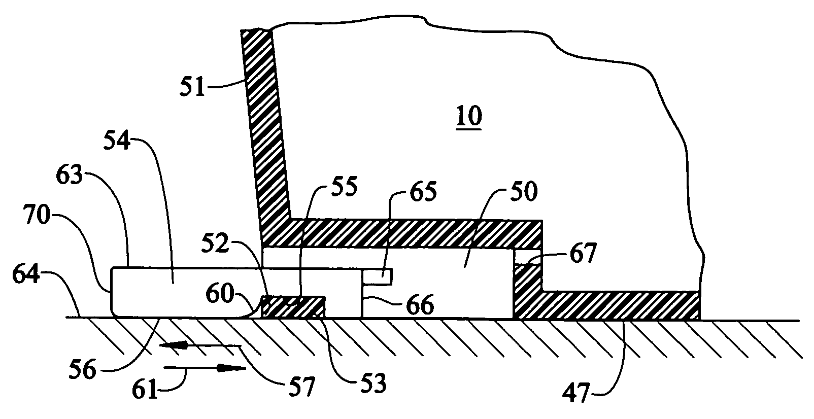
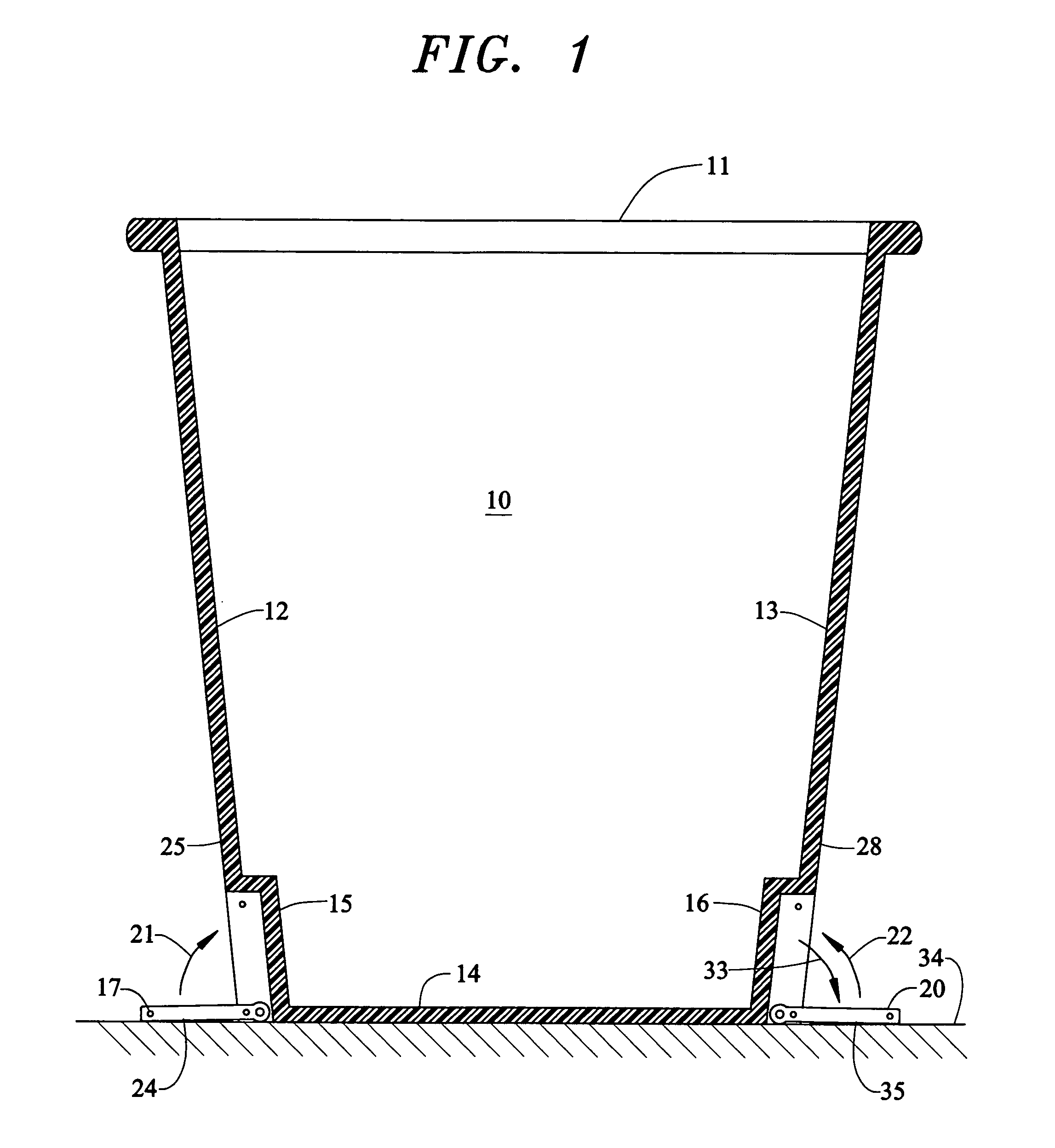
[0025]As best illustrated in FIG. 1, a generally rectangular waste receptacle 10 is provided with an open top 11 for receiving a flexible, removable trash bag (not shown in the drawing). A pair of opposing lateral sides 12, 13 extend from the open top 11 to a generally flat base 14. Recessed housings 15, 16 are formed in opposite respective sides 12, 13 of the receptacle 10. The housings 15, 16, moreover, are formed in the receptacle 10 adjoining the base 14.

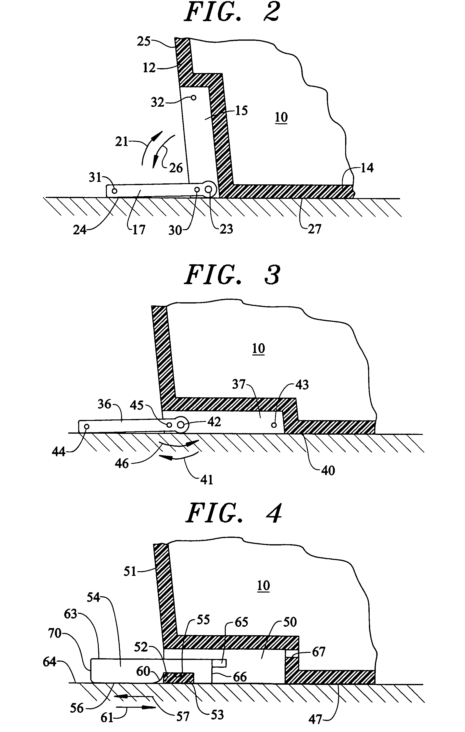
[0026]In accordance with a feature of the invention foot pedals 17, 20 each are selectively foldable in the direction of respective arrows 21, 22 into the individual housings 15, 16. A specific structure that characterizes features of this invention is shown in FIG. 2. As illustrated, the foot pedal 17 has a shaft 23 that is received in corresponding journals (not shown in the drawing) that are formed in the recessed housing 15. In this manner, the foot pedal 17 can be pivoted back into the recessed housing 15 in the direction o...


PUM


Abstract

A stable waste receptacle has in the preferred embodiment, at least two foot pedals mounted on opposite sides of the receptacle, at the receptacle's base. Recessed housings are formed in the base and sides to permit the foot pedals to be withdrawn from the housings to stabilize the receptacle during trash bag removal or to be pressed back into the respective housings for telescopically stacking multiple receptacles. Detents are provided to retain the foot pedals releasably in the extended and retracted positions.

Description

CROSS-REFERENCE TO RELATED APPLICATIONS[0001]NoneFEDERALLY SPONSORED RESEARCH OR DEVELOPMENT[0002]NoneSEQUENCE LISTING[0003]NoneBACKGROUND OF THE INVENTION[0004]This invention relates to improved waste receptacles and, more particularly, to receptacles with foot pedals for selective extension from the receptacle base to aid in flexible trash bag removal, and the like.[0005]Waste receptacles that support flexible trash bags are popular and useful items for home and for commercial use. Ordinarily, a waste receptacle holds a flexible trash bag in an upright position with the unsealed end of the bag uppermost and open within the receptacle. Waste, trash and the like are deposited in the open bag. When it becomes necessary or desirable to remove the flexible bag for disposal, it is customary to grasp the waste receptacle with one hand and gather together with the other hand the open end of the flexible bag. The flexible bag, so held, is then withdrawn from the waste receptacle for dispos...

Claims


Application Information

Patent Timeline
Patent Type & Authority Patents(United States)
IPC IPC(8): B65D90/12B65D1/40B65F1/06
CPCB65F1/068Y10S220/908
Inventor ROBINSON, C. BIVINS
Owner ROBINSON C BIVINS
Why Eureka
Try Eureka