Mounting Unit for Solar Electricity Generation Systems and Improved Installation Method

a solar energy generation system and solar panel technology, applied in the direction of solar heat collector details, solar heat collector mounting/support, light and heating apparatus, etc., can solve the problems of affecting the standardization of solar panel mounting and installation, limited control, and high labor intensity of skilled technicians, so as to optimize the convection cooling of the solar panel, reduce installation time and cost, and save labor costs

Inactive Publication Date: 2016-09-01
CUSHING ENERGY LTD
View PDF9 Cites 16 Cited by
  • Summary
  • Abstract
  • Description
  • Claims
  • Application Information

AI Technical Summary

Benefits of technology

[0022]The solar electric generation system described herein provides many advantages over conventional systems. First, the mounting unit of the solar electric generation system integrates all of the key features required to mount a solar panel and power conversion device. According to one embodiment, the mounting unit may be implemented as a single plastic molded unit. The use of a plastic material for the mounting unit (or other electrically inert material) eliminates the need for the mounting unit to be electrically grounded. Unlike conventional systems, the solar panel and / or power conversion device may be preassembled onto the mounting unit prior to shipment of the unit to the solar generation site, in some embodiments. This significantly reduces installation time and cost over conventional assembly methods, which assemble the solar panels onto a racking assembly on-site. The presently disclosed mounting units, which may come preassembled with solar panels and / or power conversion devices, may also be stacked in a manner that enables efficient storage and shipment of multiple units to the solar generation site without damaging the solar panels. Each mounting unit is also advantageously designed with an air channel that optimizes convection cooling of the solar panel and optionally the power conversion device, and may include a reflective surface that further increases efficiency.

Problems solved by technology

These conventional systems require substantial site preparation activities and in-field labor by skilled technicians that are expensive and provide limited opportunity to control or inspect the work product during construction.
Thus, the conventional approach significantly hampers the ability for solar panel mounting and installation to become more standardized, and hence more cost effective.
Further, conventional systems do not seek to optimize natural convection forces for purposes of cooling the solar panel and associated power conversion devices, and thus, fail to optimize the solar conversion efficiency of the system electric generation system.

Method used


Image

  • Mounting Unit for Solar Electricity Generation Systems and Improved Installation Method
  • Mounting Unit for Solar Electricity Generation Systems and Improved Installation Method
  • Mounting Unit for Solar Electricity Generation Systems and Improved Installation Method

Examples


Embodiment Construction

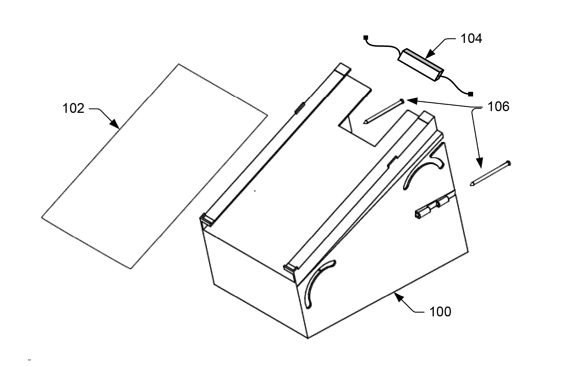
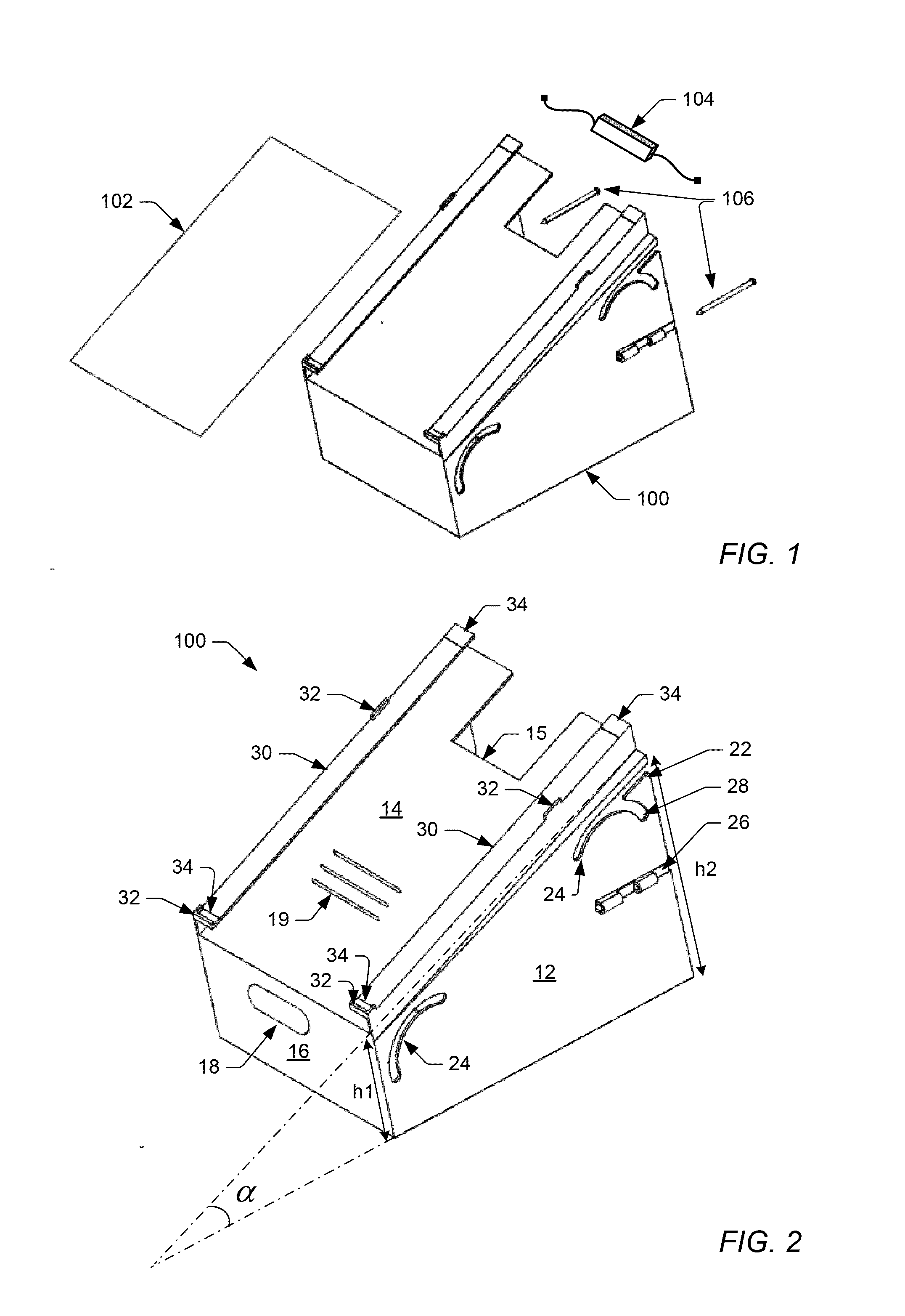
[0036]Referring now to the invention in more detail, FIG. 1 shows one embodiment of a solar electricity generation system comprising a mounting unit 100, a solar panel 102 that converts light into electricity, a power conversion device 104 that converts the DC output of solar panel 102 into the proper AC current and voltage types and levels to match the requirements for its connection to a load or electric distribution system, and two hinge pin-stakes 106. Together these components constitute one preferred embodiment of a solar electricity generation system. Additional features of the solar electricity generation system are illustrated in FIGS. 2-11 and discussed in more detail below. While the solar electricity generation system described herein is generally designed for a ground mounted installation, one skilled in the art would readily understand how it may be alternatively installed on any substantially horizontal surface, such as a building rooftop, scaffolding, frame, trailer ...


PUM


Abstract

The present invention provides a mounting unit for solar panels that simplifies the complexity of storage, transit and in-field installation of solar electric generation systems. According to one embodiment, the mounting unit comprises a top panel, a bottom panel and a pair of panel guides, each formed integral with and adjacent to an opposing side of the top panel. Each panel guide includes a horizontal portion for supporting a solar panel and a vertical portion for providing an air channel between a bottom surface of the solar panel and an upper surface of the top panel. The air channel enables natural convection to cool the solar panel and optionally a power conversion device used within the system, thereby improving the solar conversion efficiency of the system. An improved method for installing a solar electric generation system is also provided herein.

Description

BACKGROUND OF THE INVENTION[0001]1. Field of the Invention[0002]The present invention is in the technical field of solar electricity generation systems. More particularly, the present invention is in the technical field of solar panel mounting and installation assemblies within solar electric generation systems.[0003]2. Description of the Relevant Art[0004]The following descriptions and examples are provided as background only and are intended to reveal information that is believed to be of possible relevance to the present invention. No admission is necessarily intended, or should be construed, that any of the following information constitutes prior art impacting the patentable character of the subject matter claimed herein.[0005]Within a solar electric generation system that utilizes solar panels, conventional systems for mounting and installing the solar panels rely on the delivery and in-field assembly of a large number of individual metal components at the site of the generatio...

Claims


Application Information

Patent Timeline
Patent Type & Authority Applications(United States)
IPC IPC(8): H01L31/042H02S20/10H02S20/23F16M11/04
CPCH02S20/00H02S20/23H02S20/10F16M11/04F24S25/11F24S25/15F24S25/65F24S80/457F24S2025/02F24S2025/6007H01L31/02H02S20/24H02S20/30H02S40/42Y02B10/10Y02B10/20Y02E10/47Y02E10/50F24S25/00
Inventor BRADY, COLETOLHURST, WILLIAM
Owner CUSHING ENERGY LTD
Why Eureka
Try Eureka