Systems and methods for extending the useful life of optical sensors

a technology of optical sensors and useful life, applied in the field of sensors, can solve the problems of limited useful life of the sensor that utilizes fluorescent indicator molecules as a component to recognize and convert the presence of substances into measurable signals, and the useful life of the fluorescent indicator molecules is typically no longer fluorescent, so as to increase increase the useful product life of the optical sensor. , the effect of increasing the useful life of the indicator molecules

Active Publication Date: 2008-05-20
SENSEONICS INC
View PDF13 Cites 39 Cited by
  • Summary
  • Abstract
  • Description
  • Claims
  • Application Information

AI Technical Summary

Benefits of technology

[0014]In one aspect, the present invention provides a method for increasing the useful lifetime of an optical sensor that, when activated, is configured to obtain data regarding the presence or concentration of a substance within a certain area at least once every X amount of time (e.g., seconds, minutes, hours) for a continuous period of time. The method includes the steps of: (a) configuring the optical sensor so that the duty cycle of the radiant source is greater than 0% but less than 100% during the period of time when the optical sensor is active; (b) positioning the optical sensor at a location within the area; (c) activating the optical sensor for a period of Z amount of time after performing step (b), wherein Z is greater than 0; (d) operating the radiant source so that the duty cycle of the radiant source is greater than 0% but less than 100% during the Z amount of time when the optical sensor is active; and (e) de-activating the optical sensor after the Z amount of time has elapsed.
[0020]In another aspect, the present invention provides an optical sensor having a cooling system configured to lower the temperature of the indicator molecules. Lowering the temperature of the indicator molecules reduces the rate of photo-oxidation, and, thus, increases the useful life of the indicator molecules.

Problems solved by technology

One particular challenge in commercializing such optical sensors as the one described above is to provide for a useful period of shelf and / or operational lifetime.
Unfortunately, light catalyzed oxidation (also termed photo-oxidation or photobleaching) is a common photochemical reaction that occurs with many indicator molecules.
The oxidized product species is typically no longer fluorescent, and therefore no longer useful.
A sensor that utilizes fluorescent indicator molecules as a component to recognize and convert the presence of a substance into a measurable signal is limited in its useful life by the degradation and ultimate loss of signal caused by photobleaching (or photo-oxidation).
This incompatibility in component operational lifetime ultimately limits a product to the shorter useful life of the indicator chemistry.

Method used


Image

  • Systems and methods for extending the useful life of optical sensors
  • Systems and methods for extending the useful life of optical sensors
  • Systems and methods for extending the useful life of optical sensors

Examples


Embodiment Construction

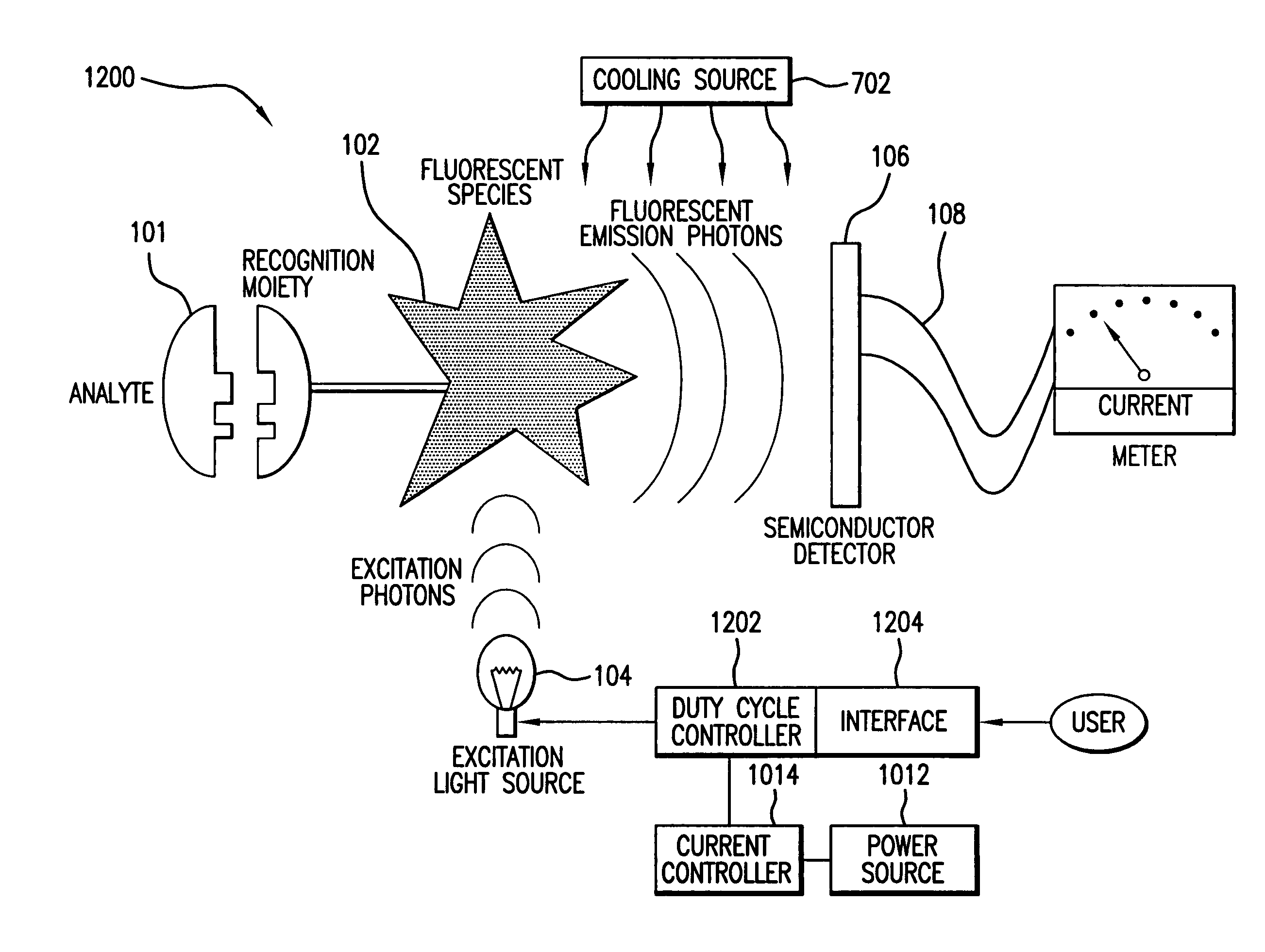
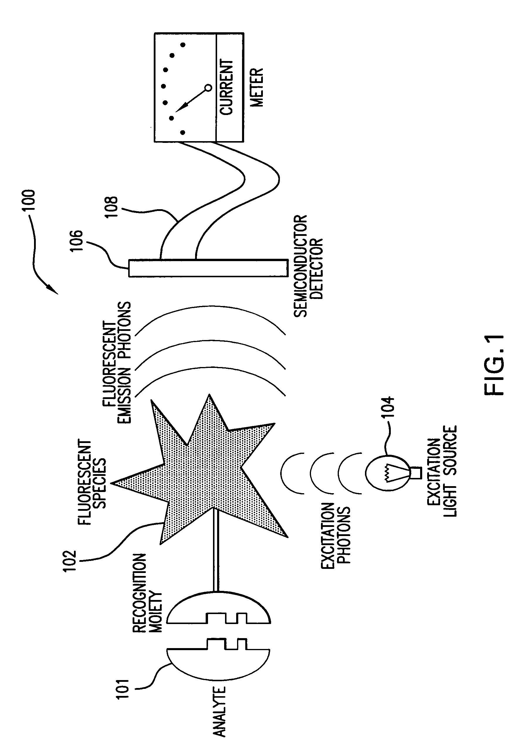
[0045]FIG. 1 shows a schematic illustration of a representative conventional optical sensor 100 for detecting the presence or concentration of a substance 101. Sensor 100 includes indicator molecules 102, a light source 104, and a photoelectric transducer 106 (or “photodetector 106”). It can be seen from the graphic in FIG. 1 that the indicator molecules 102 are a key element in converting the presence and concentration of the substance to a measurable signal (e.g., a measurable electrical current output 108 from photodetector 106).

[0046]As discussed above, photo-oxidation causes the indicator molecules to be the “weakest” component of sensor 100. That is, photo-oxidation causes the indicator molecules to degrade sooner than the other components of sensor 100. The surrounding components, such as light source 104 and photodetector 106, have useful lifetimes typically exceeding ten years. However, the indicator molecules can be degraded under typical operating conditions within hours ...


PUM

PropertyMeasurementUnit
drive currentaaaaaaaaaa

Abstract

The present invention provides a method for increasing the lifetime of an optical sensor. In one aspect, the method includes the step of configuring the optical sensor so that the duty cycle of sensor's radiant source is less than 100% over a continuous period amount of time when the sensor is periodically obtaining data regarding an analyte. By operating the sensor according to the above inventive method, the indicator molecules of the optical sensor are not excited during the entire continuous period of time during which the sensor is needed to provide data regarding the presence or concentration of a substance. Thus, the method increases the life of the indicator molecules.

Description

BACKGROUND OF THE INVENTION[0001]1. Field of the Invention[0002]The present invention relates to sensors that detect the presence or concentration of a particular substance using a radiant source, a photodetector and indicator molecules, which have an optical characteristic that is affected by the presence of the substance. Such sensors are referred to herein as “optical sensors.” In one aspect, the present invention relates to systems and methods for extending the useful life of optical sensors.[0003]2. Discussion of the Background[0004]U.S. Pat. No. 5,517,313, the disclosure of which is incorporated herein by reference, describes a sensing device comprising a radiant source (e.g., a light-emitting diode—“LED”), fluorescent indicator molecules, and a photoelectric transducer (e.g., a photodiode, phototransistor, photomultiplier, or other photodetector). The sensing device may also include a high-pass or bandpass filter. Broadly speaking, in the context of the field of the present i...

Claims


Application Information

Patent Timeline
Patent Type & Authority Patents(United States)
IPC IPC(8): G01N21/64A61B5/00
CPCA61B5/14532A61B5/1455G01N21/6428A61B5/14556A61B5/1459A61B2560/0209A61B5/00G01N21/64
Inventor COLVIN, JR., ARTHUR EARLLESHO, JEFFERY C.LORENZ, CARRIE R.
Owner SENSEONICS INC
Why Eureka
Try Eureka