
Die package with asymmetric leadframe connection

a technology of leadframe and die package, which is applied in the direction of semiconductor devices, semiconductor/solid-state device details, electrical devices, etc., can solve the problems of damage or failure of the package, and downward force on the top of the semiconductor die, so as to prevent excessive movement of the semiconductor die and improve the balance of the leadframe

Active Publication Date: 2008-05-20
SANDISK TECH LLC
View PDF14 Cites 23 Cited by
  • Summary
  • Abstract
  • Description
  • Claims
  • Application Information

AI Technical Summary

Benefits of technology

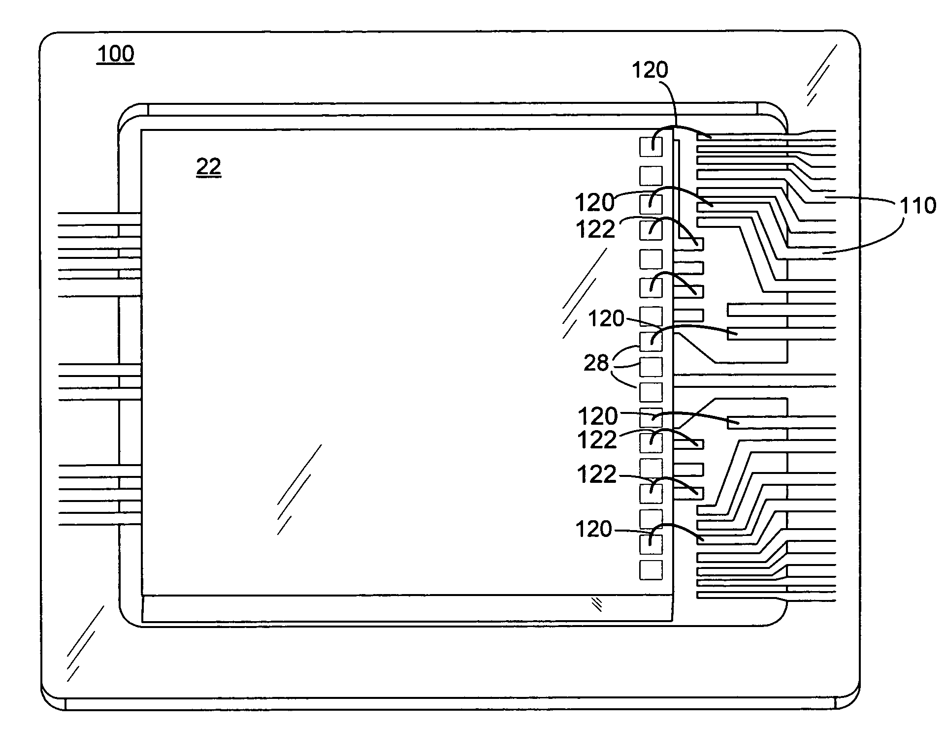
[0012]One or more semiconductor die may be supported on the leadframe by being mounted to the elongated electrical leads. Thus, the elongated electrical leads serve a dual purpose of carrying electrical signals to and from the semiconductor die, as well as physically supporting the semiconductor die on the leadframe. Once the one or more semiconductor die are attached to the leadframe, the die bond pads along the single edge of the die may be wire-bonded to both the electrical leads from the first side of the leadframe and the elongated electrical leads extending from the second side of the leadframe. In embodiments, the elongated electrical leads allow the semiconductor die to be used in an industry standard pinout configuration.
[0013]After the wire-bond process, the semiconductor die, wire-bonds and portions of electrical leads may be encapsulated in molding compound to form a semiconductor die package. In a further embodiment of the present invention, before encapsulation, a spacer layer may be affixed to surfaces of the elongated electrical leads opposite the surfaces of the leads supporting the semiconductor die. The spacer layer may be a dielectric material such as for example a polyimide film or tape, or various epoxy resins. The spacer layer provides at least two benefits. First, the spacer layer fortifies and improves the balance of the leadframe during the molding process to prevent excessive movement of semiconductor die and jeopardy to the wire bond between the die and leadframe. Secondly, the spacer layer insulates and prevents exposure of the elongated electrical leads outside of the package.

Problems solved by technology

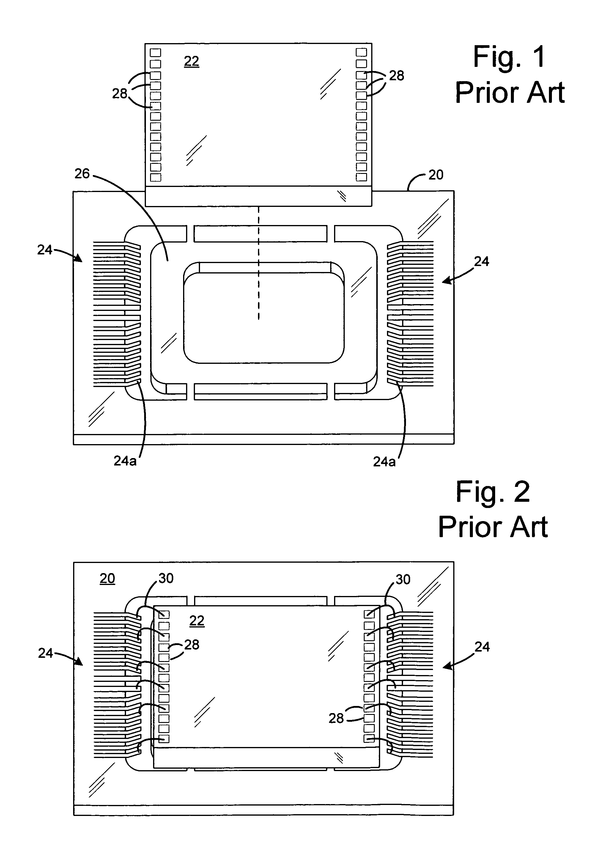
Such movement can break or short one or more of the wire bonds 28, resulting in damage or complete failure of the semiconductor package.
As there may be fifty or more wire bonds in a package, this can become a significant problem if the semiconductor die is not properly balanced during the molding process.
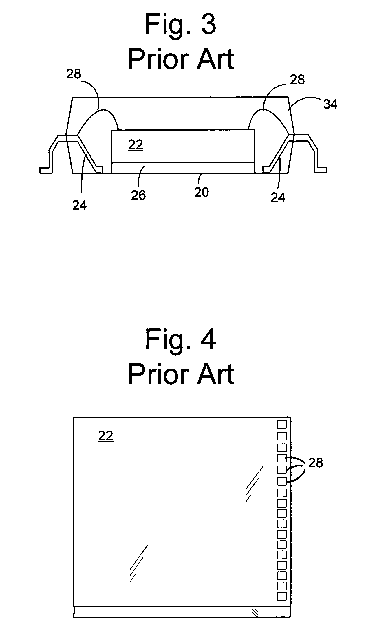
This results in a downward force on top of the semiconductor die.
This again may result in damage or failure of the package.

Method used


Image

  • Die package with asymmetric leadframe connection
  • Die package with asymmetric leadframe connection
  • Die package with asymmetric leadframe connection

Examples


Embodiment Construction

[0024]Embodiment to the present invention will now be described in reference to FIGS. 5-10 which in general relate to a method of fabricating a semiconductor package, and a semiconductor package formed thereby. It is understood that the present invention may be embodied in many different forms and should not be construed as being limited to the embodiments set forth herein. Rather, these embodiments are provided so that this disclosure will be thorough and complete and will fully convey the invention to those skilled in the art. Indeed, the invention is intended to cover alternatives, modifications and equivalents of these embodiments, which are included within the scope and spirit of the invention as defined by the appended claims. Furthermore, in the following detailed description of the present invention, numerous specific details are set forth in order to provide a thorough understanding of the present invention. However, it will be clear to those of ordinary skill in the art th...


PUM


Abstract

A leadframe for a semiconductor package is disclosed including electrical leads which extend from one side of the leadframe to an opposite side of the leadframe, where electrical connection may be made with the semiconductor die at the second side of the leadframe. The semiconductor die may be supported on the leads extending across the leadframe. The package may further include a spacer layer affixed to the electrical leads to fortify the semiconductor package and to prevent exposure of the electrical leads during the molding of the package.

Description

BACKGROUND OF THE INVENTION[0001]1. Field of the Invention[0002]Embodiments of the present invention relate to a method of a semiconductor package, and a semiconductor package formed thereby.[0003]2. Description of the Related Art[0004]As the size of electronic devices continue to decrease, the associated semiconductor packages that operate them are being designed with smaller form factors, lower power requirements and higher functionality. Currently, sub-micron features in semiconductor fabrication are placing higher demands on package technology including higher lead counts, reduced lead pitch, minimum footprint area and significant overall volume reduction.[0005]One branch of semiconductor packaging involves the use of a leadframe, which is a thin layer of metal on which one or more semiconductor die are mounted. The leadframe includes electrical leads for communicating electrical signals from the one or more semiconductors to a printed circuit board or other external electrical ...

Claims


Application Information

Patent Timeline
Patent Type & Authority Patents(United States)
IPC IPC(8): H01L23/495
CPCH01L23/4951H01L23/49551H01L23/49558H01L23/49575H01L2224/48091H01L2224/48247H01L2225/06562H01L2924/00014H01L24/48H01L2924/01087H01L2224/32145H01L2224/32245H01L2224/73265H01L2924/00012H01L24/49H01L24/73H01L2224/05553H01L2224/49109H01L2924/10161H01L2924/14H01L2924/181H01L2924/18165H01L2924/00H01L2224/45099H01L2224/45015H01L2924/207H01L23/495
Inventor LEE, MING HSUNLIAO, CHIH-CHINYU, CHEEMENTAKIAR, HEM
Owner SANDISK TECH LLC
Learn More