Self-adjust able anti-chucking device

a technology of anti-chucking device and self-adjusting, which is applied in the direction of roofs, doors, wing accessories, etc., can solve the problems of chucking, lifting the liftgate to rattle, or expanding the sides of the opening in the base, and the latch alone is not enough to hold the liftgate in pla

Inactive Publication Date: 2006-05-11
FORD GLOBAL TECH LLC
View PDF19 Cites 13 Cited by
  • Summary
  • Abstract
  • Description
  • Claims
  • Application Information

AI Technical Summary

Benefits of technology

[0007] When the liftgate is closed and latched, the slider block in the wedge portion contacts the oblique surface of the base portion and pushes the slider block against the biasing force of the resilient member. The friction between the slider block and the oblique surface securely holds the liftgate and prevents the liftgate from excessive movement in the Y-direction while still allowing the liftgate to move slightly in the Z-direction. Moreover, if the liftgate shifts position slightly due to, for example, twisting, the biasing force of the resilient member will cause the slider block to shift to compensate for any change in the liftgate position relative to the vehicle body.
[0008] The inventive self-adjusting wedge configuration prevents the liftgate from impacting the vehicle body without creating stress in the anti-chucking device itself. Instead, the resilient member absorbs any forces caused by movement of the liftgate, repositioning the slider block so that it remains firmly engaged against the oblique surface even if the gap between the edge of the liftgate and the vehicle body changes size as the vehicle moves.

Problems solved by technology

However, the latch alone is not enough to hold the liftgate in place due to the forces encountered by the liftgate, particularly while the vehicle is driven over rough surfaces.
The large size and weight of the liftgate will therefore cause the liftgate to twist, creating high stress points on the latch and causing the liftgate to rattle, or “chuck,” against the side of the vehicle, particularly against the D-pillars.
Over time, however, repeated Z-direction forces on the male pin within the female base will create stress on the pin itself, potentially expanding the sides of the opening in the base and allow chucking and rattling.
If the stress on the pin is great enough, the pin itself may break off, causing the chucking to be great enough to potentially cause vehicle damage.

Method used


Image

  • Self-adjust able anti-chucking device
  • Self-adjust able anti-chucking device
  • Self-adjust able anti-chucking device

Examples


Embodiment Construction

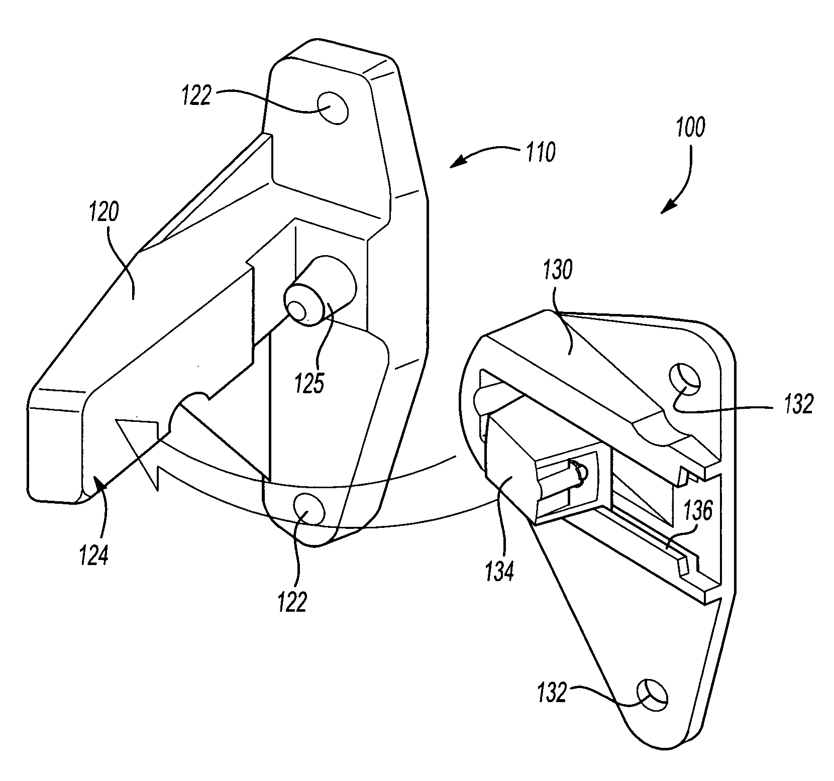
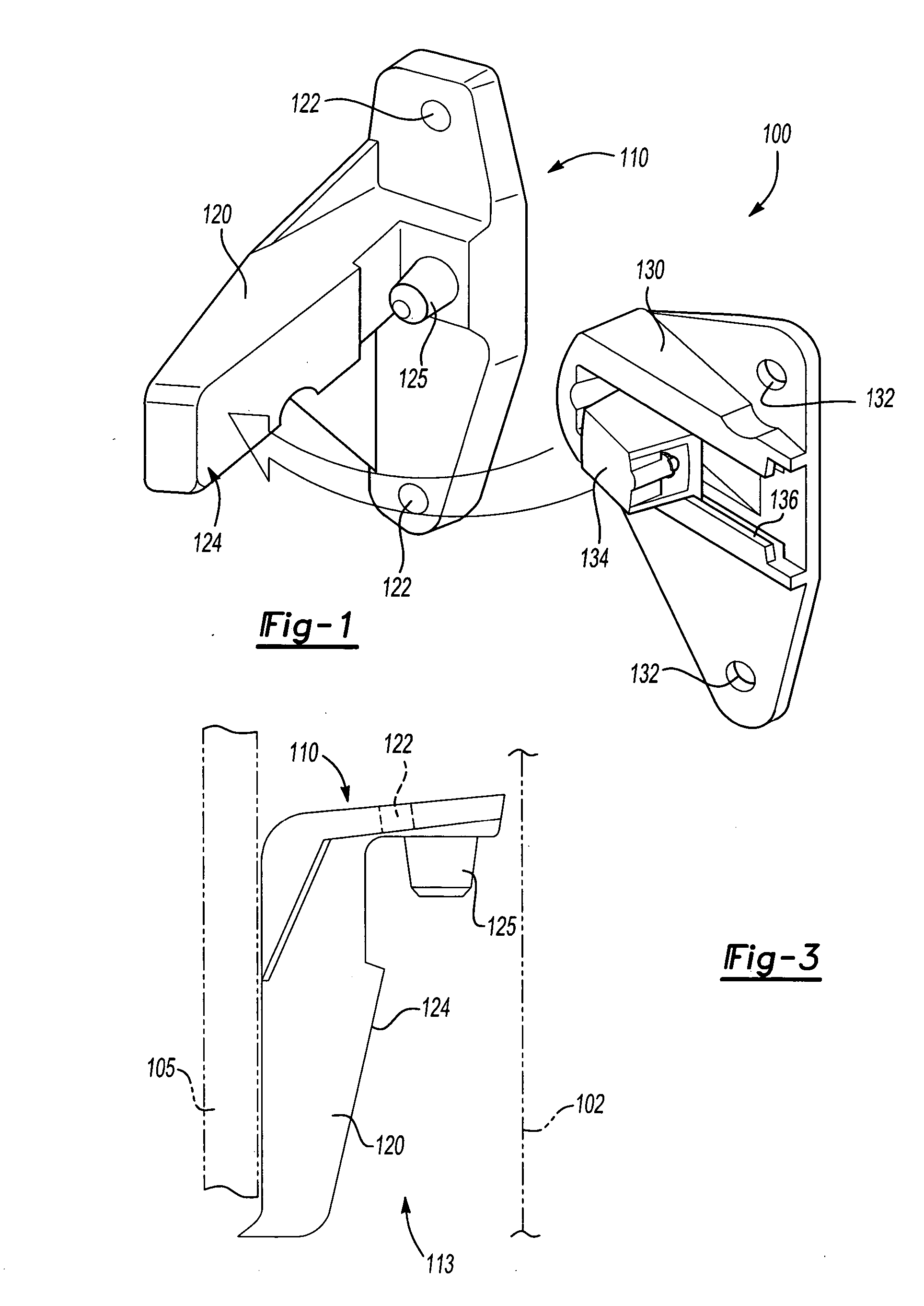
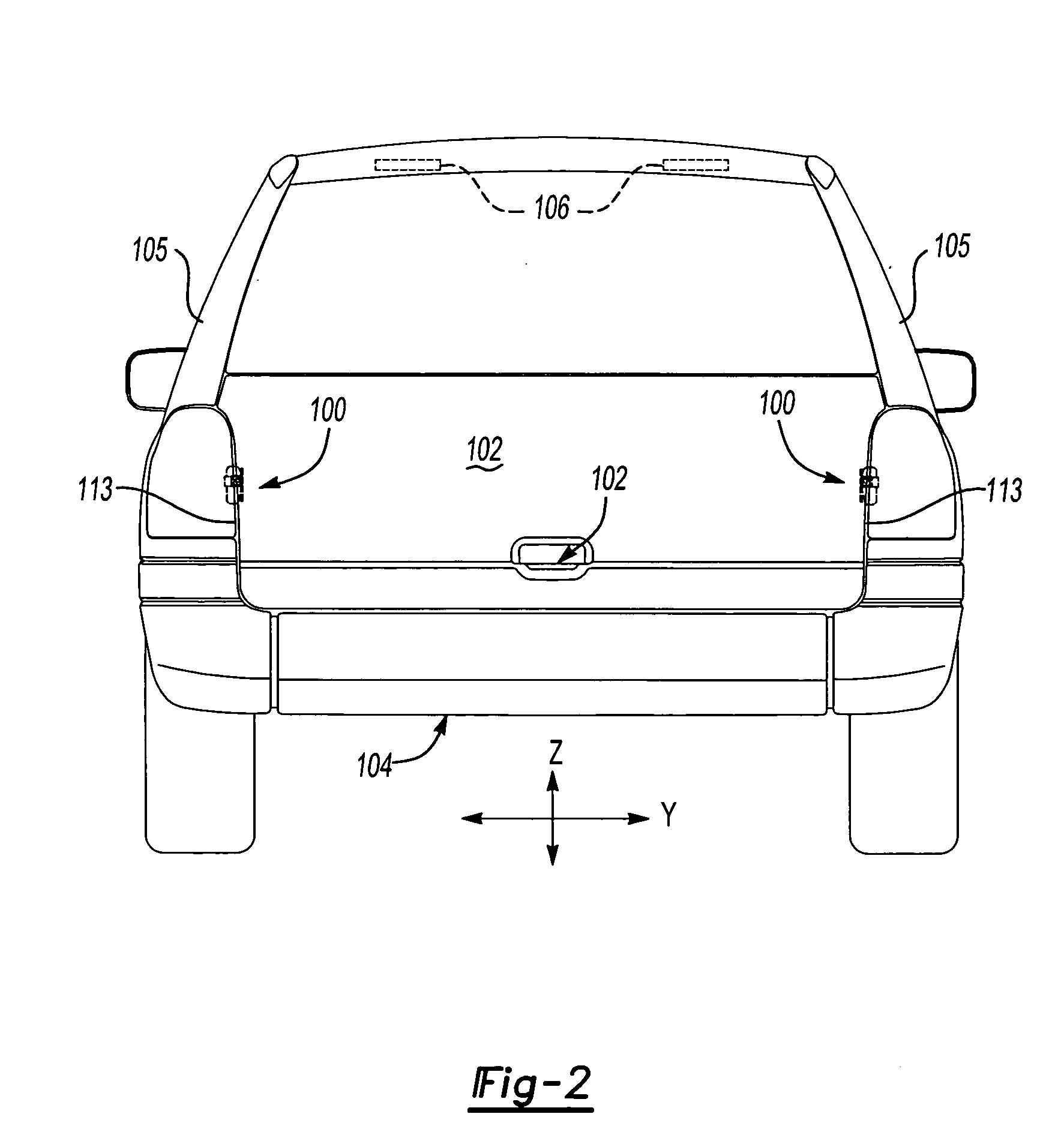
[0016] Referring to FIGS. 1 and 2, a self-adjustable anti-chucking device 100 is designed to fit between a side edge of a liftgate 102 and a portion of a vehicle body 104, such as a D-pillar 105. As shown in FIG. 2, the liftgate 102 is secured to the vehicle at its top edge by a hinge mechanism 106 and is held in place by a latch 108 when the liftgate 102 is closed. The anti-chucking device 100 prevents excessive movement of the liftgate 102 relative to the vehicle body 104 in the Y-direction while still allowing the liftgate 102 to move in the Z-direction to accommodate any play in the hinge 106 and / or latch 108.

[0017] In the examples shown in the Figures and discussed below, only a left-handed device 100 for the left side of the vehicle is shown for clarity. Those of skill in the art will understand that the right-handed device 100 for the right side of the vehicle will be a mirror image of the left-handed structure illustrated and described below.

[0018] The anti-chucking device...


PUM


Abstract

A self-adjustable anti-chucking device for a vehicle liftgate includes a wedge portion that is attachable to the liftgate and a base portion that is attachable to a vehicle body. The wedge portion includes a wedge-shaped slider block that is biased by a resilient member. The base portion includes an oblique surface shaped to contact a surface of the slider block. When the liftgate is closed and latched, the friction between the slider block and the oblique surface and the biasing force of the resilient member securely hold the liftgate in place. If the liftgate shifts position, the biasing force of the resilient member will cause the slider block to shift to compensate for any change in the liftgate position relative to the vehicle body.

Description

TECHNICAL FIELD [0001] The present invention relates to vehicle liftgate components, and more particularly to a device for preventing chucking of the liftgate. BACKGROUND OF THE INVENTION [0002] Sport utility vehicles, trucks, and other larger vehicles often have a liftgate to provide user access to the rear of the vehicle. The liftgate is held closed by a latch disposed on a bottom edge of the liftgate. However, the latch alone is not enough to hold the liftgate in place due to the forces encountered by the liftgate, particularly while the vehicle is driven over rough surfaces. Although the latch secures the liftgate on its bottom edge and hinges secure the liftgate on its top edge, this still leaves the side edges of the liftgate free to move relative to the vehicle. The large size and weight of the liftgate will therefore cause the liftgate to twist, creating high stress points on the latch and causing the liftgate to rattle, or “chuck,” against the side of the vehicle, particula...

Claims


Application Information

Patent Timeline
Patent Type & Authority Applications(United States)
IPC IPC(8): B60J5/00
CPCE05F5/022E05F7/04E05Y2900/546
Inventor WANG, JOHNROGERS, DAVID
Owner FORD GLOBAL TECH LLC
Why Eureka
Try Eureka