Virtual mirror

a virtual mirror and mirror technology, applied in the field of mirrors, can solve the problems of obstruction and limitations of the field of view, the overlap of the already narrow field of view, and the blind zone associated with the conventional mirror

Active Publication Date: 2008-05-20
MINNESOTA UNIV OF
View PDF101 Cites 130 Cited by
  • Summary
  • Abstract
  • Description
  • Claims
  • Application Information

AI Technical Summary

Problems solved by technology

A first of these disadvantages is the blind zones associated with a conventional mirror.
Typically, drivers set the mirrors such that there is a great degree of overlap in these already narrow fields of view.
Obstructions and limitations to the fields of view are due to the location and size of real mirrors.
Another problem with conventional mirrors is that the view from the mirror to the rear or side of the vehicle is often obstructed.
For example, a passenger's head or vehicle pillars may obstruct the rearward or sideward looking views from the driver or from the mirror.
Similarly, on large vehicles, such as trucks and sport utility vehicles, the views from the mirrors can be obstructed by portions of the vehicle body itself.
Another disadvantage presented by conventional mirrors is vibration.
While this disadvantage is not as pronounced on small passenger cars, it presents a great deal of difficulty on large, commercial vehicles.
As such a vehicle encounters uneven road surfaces, induced torques are transmitted to the mirror mounting hardware which causes the mirror to vibrate.
These vibrations can be at frequencies which significantly disrupt the ability of the driver to distinguish meaningful information from the mirror.
Therefore, as the mirror oscillates back and forth, the image also oscillates back and forth with twice the magnitude of the mirror oscillation, leading to a blurred image.
Another disadvantage of conventional mirrors is that they must be quite large in order to provide a significant rearward or sideward looking view.
However, any mirror mounted forward of the operator obstructs the forward view.
Therefore, large conventional mirrors can undesirably obstruct the operator's forward looking view.
Another disadvantage arises from the fact that many commercial vehicles use convex mirrors, in addition to flat mirrors.
However, such periscopes have been found to be very large and bulky, and adversely increase the air resistance and drag of the vehicle.
In addition, such a TV monitor hooked up to a rearward looking camera does not operate satisfactorily under poor visibility conditions.
The display can also lead to confusion because of the likely absence of the right-left lateral inversion associated with a reflected image.

Method used


Image

  • Virtual mirror
  • Virtual mirror
  • Virtual mirror

Examples


Embodiment Construction

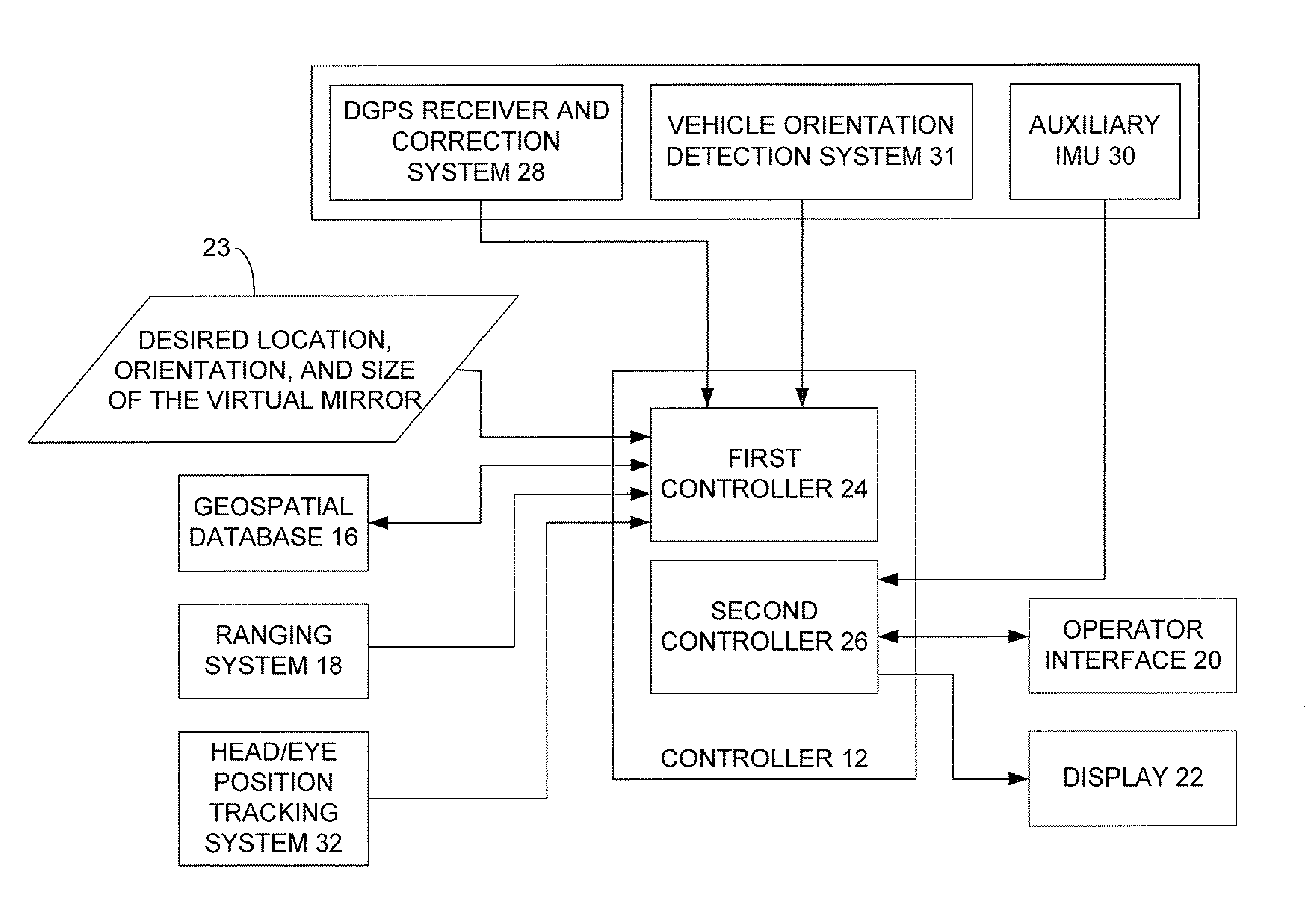
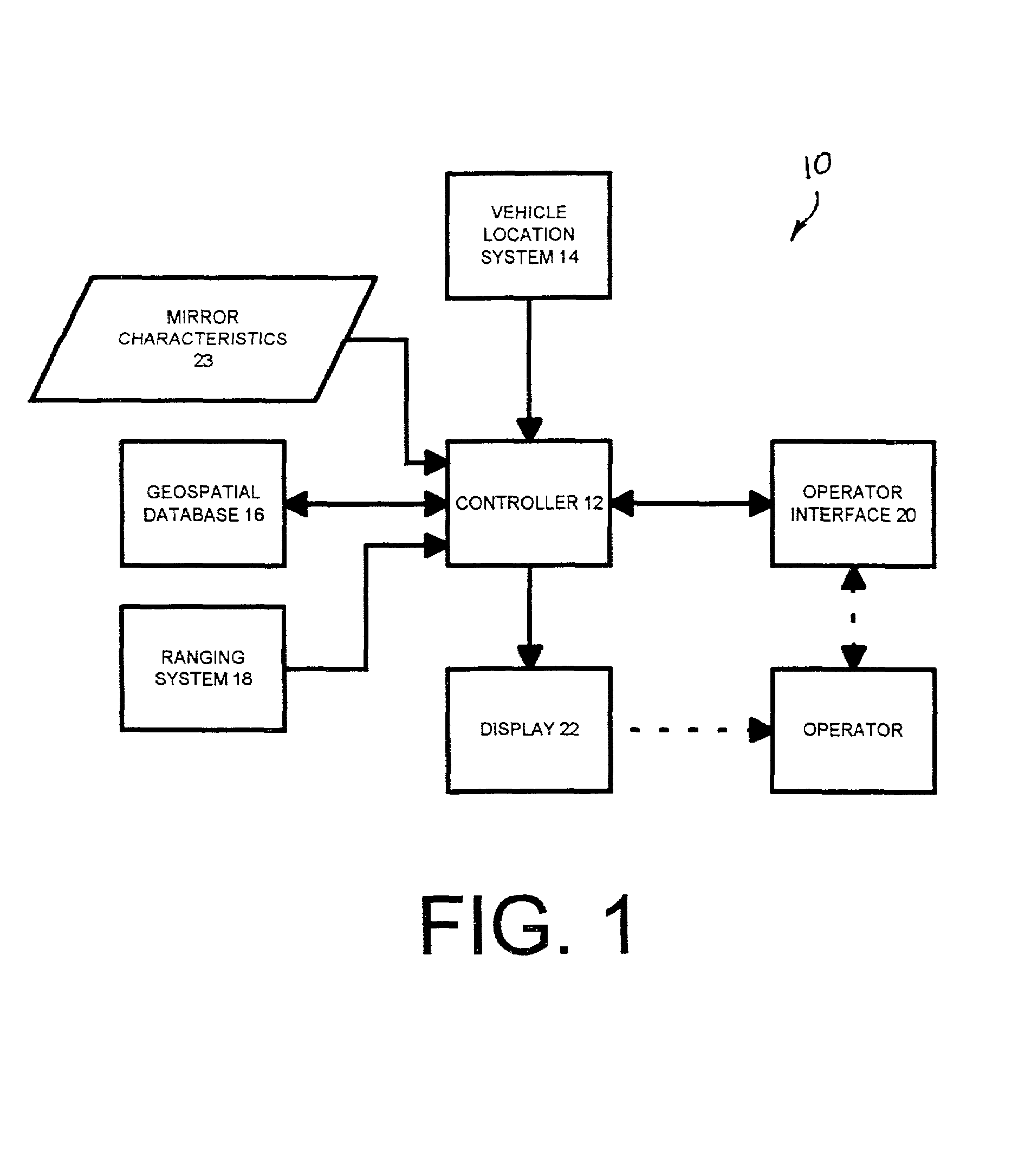
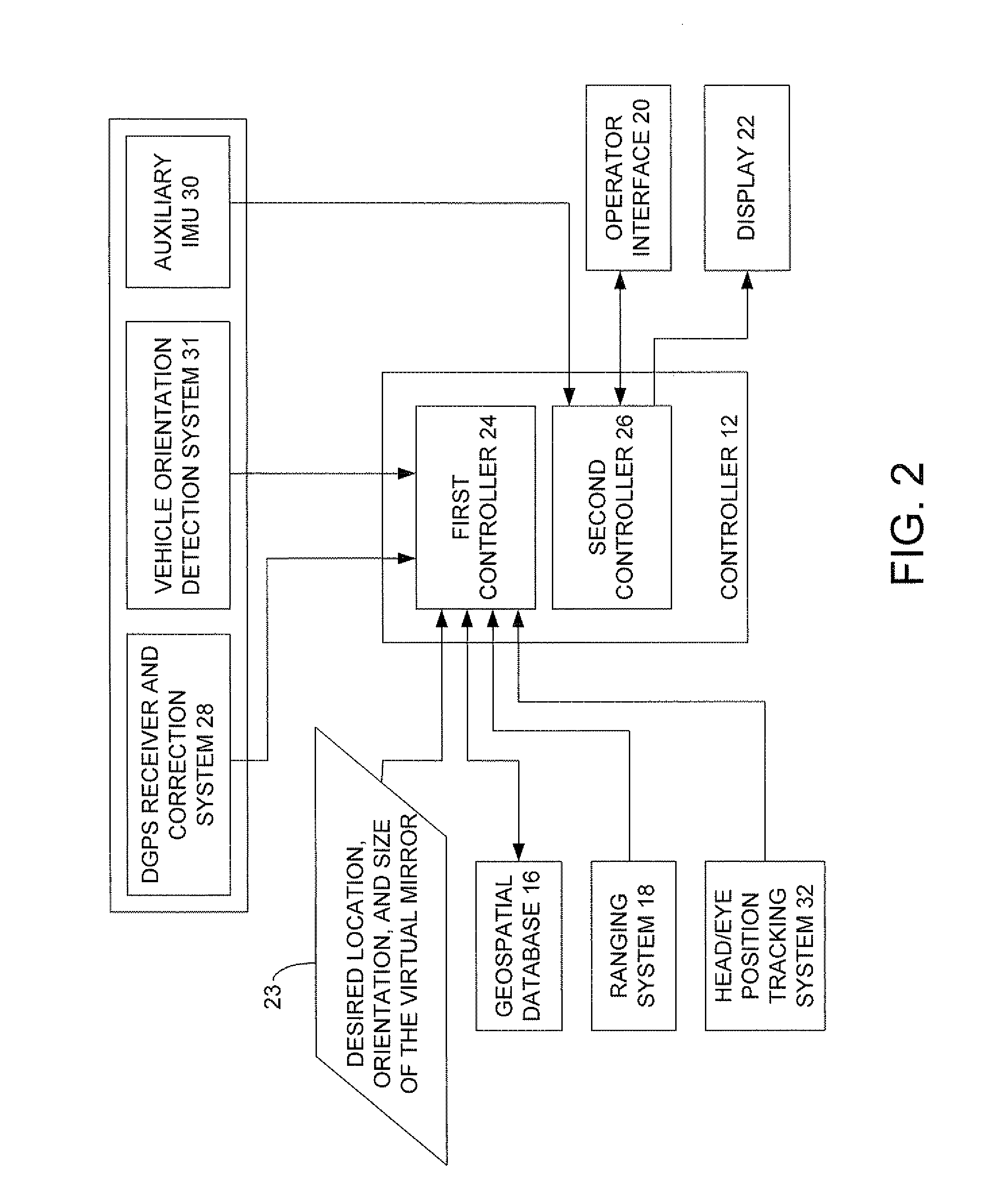
[0040]The present invention can be used with substantially any mobile body. However, the present description proceeds with respect to an illustrative embodiment in which the invention is implemented on a motor vehicle as a driver vision assist device (or virtual mirror). FIG. 1 is a simplified block diagram of one embodiment of vision assist device 10 in accordance with the present invention. Assist device 10 includes controller 12, vehicle location system 14, geospatial database 16, ranging system 18, operator interface 20 and display 22. FIG. 1 also shows that controller 12 receives, as an input, virtual mirror characteristics 23.

[0041]In one embodiment, controller 12 is a microprocessor, microcontroller, digital computer, or other similar control device having associated memory and timing circuitry. It should be understood that controller 12 can be implemented as one or more processors or computers, and that the memory can be integrated with controller 12, or be located separatel...


PUM


Abstract

A virtual mirror is rendered by a computer graphics display or screen. The display substantially replicates the optical properties of a physical mirror. The display is provided on a host vehicle.

Description

[0001]The present invention hereby incorporates by reference and claims priority from co-pending U.S. patent application Ser. No. 09 / 618,613, filed Jul. 18, 2000.BACKGROUND OF THE INVENTION[0002]The present invention deals with mirrors. More particularly, the present invention deals with a vision enhancement device in the form of a computer generated virtual replica of a mirror.[0003]Mirrors associated with motor vehicles assist the driver by providing spatial awareness of traffic conditions behind (and to the sides of) the drivers vantage point. Conventional mirrors have several disadvantages. A first of these disadvantages is the blind zones associated with a conventional mirror. Mirrors of conventional widths, on automobiles, provide a viewing angle from approximately 15 degrees to 30 degrees. Typically, drivers set the mirrors such that there is a great degree of overlap in these already narrow fields of view. Obstructions and limitations to the fields of view are due to the loc...

Claims


Application Information

Patent Timeline
Patent Type & Authority Patents(United States)
IPC IPC(8): G06T15/00B60R1/00G01C21/26G06F17/30
CPCB60R1/00G01C21/26G06F17/30241B60R2300/207B60R2300/30B60R2300/302B60R2300/60B60R2300/8046B60R2300/8066G06F16/29
Inventor DONATH, MAXSHANKWITZ, CRAIG R.CHENG, PI-MINGPARDHY, SAMEER
Owner MINNESOTA UNIV OF
Why Eureka
Try Eureka