Telescoping landing gear

a landing gear and telescoping technology, applied in the direction of vehicle maintenance, foldable cycles, vehicles, etc., can solve the problems of heavy gearing mechanism and strong force, and achieve the effects of high tensile strength, high tensile strength, and high tensile strength

Active Publication Date: 2008-05-27
THE HOLLAND GROUP
View PDF6 Cites 14 Cited by
  • Summary
  • Abstract
  • Description
  • Claims
  • Application Information

AI Technical Summary

Benefits of technology

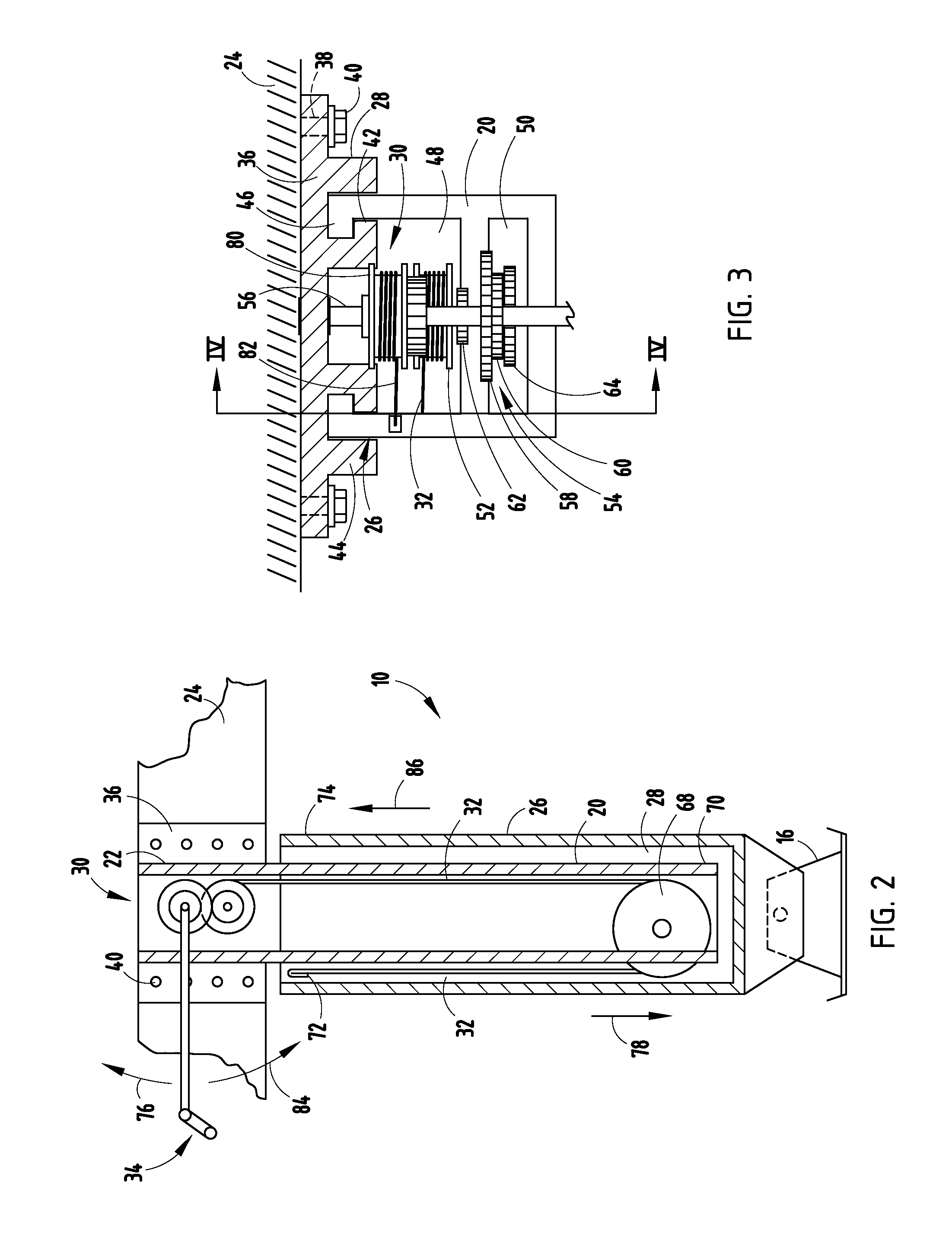
[0008]Due to the heavy weight and cumbersome nature of standard landing gears, a significant weight advantage is achieved by replacing traditional threaded rod and gear mechanisms with pulleys / rollers and fibers. The present invention provides a landing gear having fibers that are of high tensile strength and withstand fatigue and elongation. Furthermore, the fibers are resistant to heat, chemicals, and degradation without compromising excellent flexibility that is better than steel cable. Moreover, the present inventive landing gear includes an uncomplicated design, can be operated by even unskilled workers, is efficient in use, capable of a long operating life, and is particularly well adapted for the proposed use.

Problems solved by technology

Additionally, to support high-weight loads, strong, heavy gearing mechanisms are required.

Method used


Image

  • Telescoping landing gear
  • Telescoping landing gear
  • Telescoping landing gear

Examples


Embodiment Construction

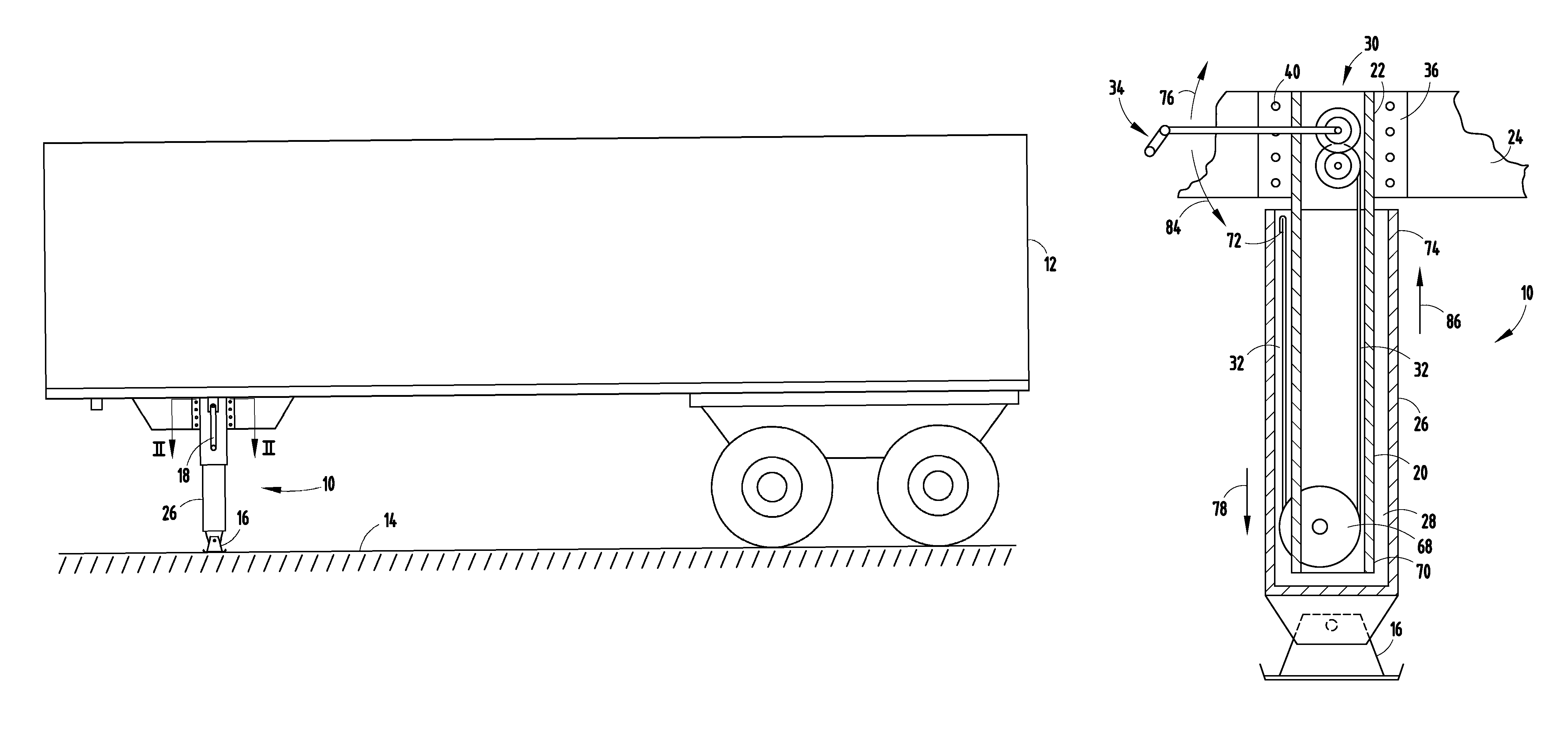
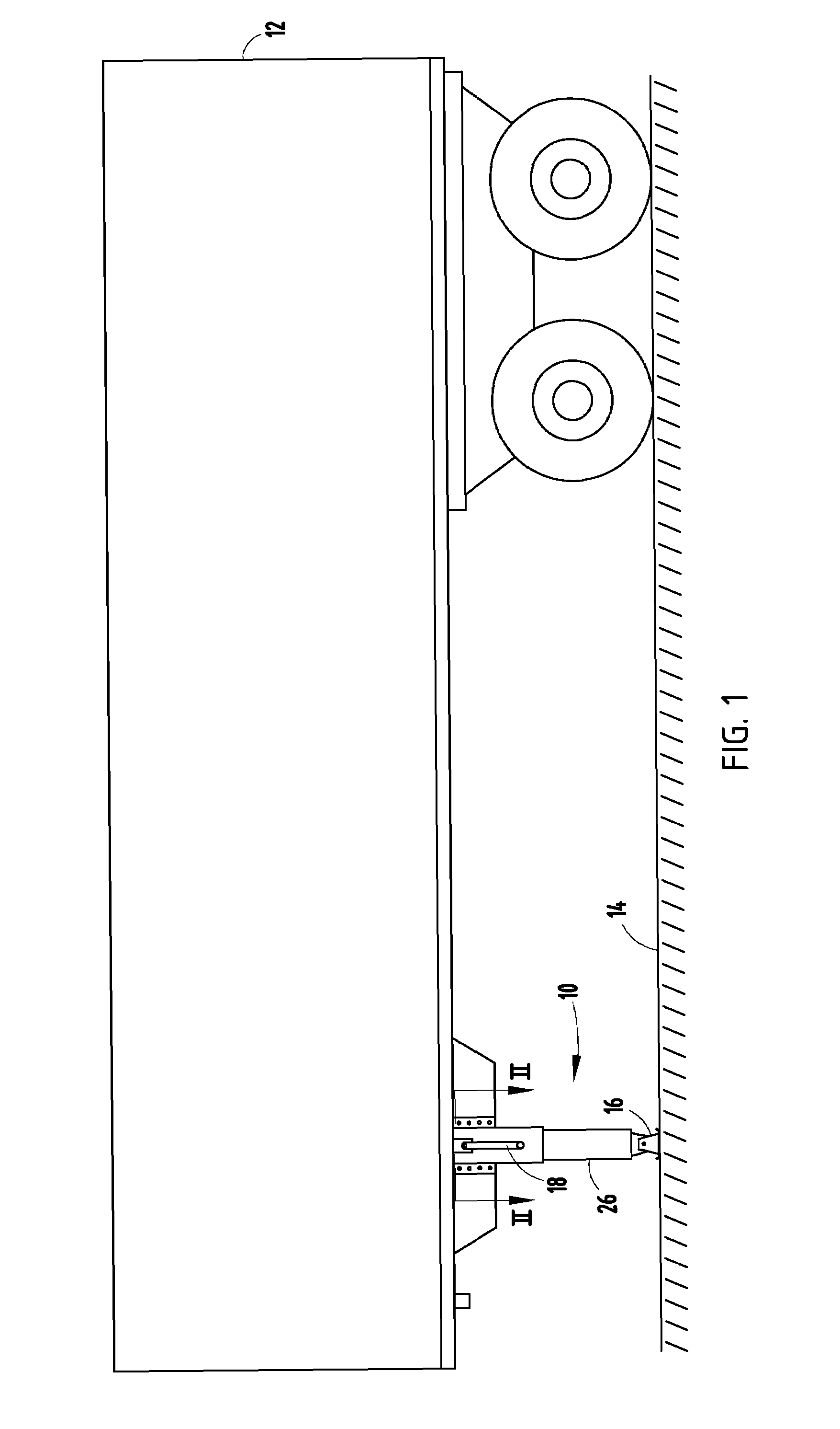
[0014]For purposes of description herein, the terms “upper,”“lower,”“right,”“left,”“rear,”“front,”“vertical,”“horizontal,” and derivatives thereof shall relate to the invention as oriented in FIG. 1. However, it is to be understood that the invention may assume various alternative orientations and step sequences, except where expressly specified to the contrary. It is also to be understood that the specific devices and processes illustrated in the attached drawings, and described in the following specification are exemplary embodiments of the inventive concepts defined in the appended claims. Hence, specific dimensions and other physical characteristics relating to the embodiments disclosed herein are not to be considered as limiting, unless the claims expressly state otherwise.

[0015]The reference numeral 10 (FIG. 1) generally designates a landing gear assembly embodying the present invention. In the illustrated example, the landing gear assembly 10 supports a forward end of a semi-...


PUM


Abstract

A landing gear assembly comprises a first leg member adapted to couple to a vehicle frame member, and a second member operably coupled to the first leg member and moveable between a raised storage position and a lowered in-use position. The landing gear assembly further comprises a flexible member operably coupled with the drive mechanism and the second leg, such that the drive mechanism extends the flexible member and moves the second leg from the storage position to the in-use position, and wherein the flexible member is adapted to support a weight exerted on the first and second legs. In certain embodiments disclosed herein, the flexible member comprises a ribbon constructed of natural fibers. Other embodiments comprise additional pulleys and flexible members adapted to raise the second leg member from the in-use position to the raised storage position.

Description

CROSS REFERENCE TO RELATED APPLICATION[0001]This application claims the benefit of U.S. Provisional Application No. 60 / 687,781, filed Jun. 6, 2005, entitled TELESCOPING LANDING GEAR, which is hereby incorporated herein by reference in its entirety.BACKGROUND OF THE INVENTION[0002]The present invention relates to a no-lube telescoping, or sliding, landing gear utilizing high strength synthetic, or natural fiber ribbons or strands as support for extending or lifting an apparatus.[0003]Landing gears are generally designed to have a gear system that motivates a landing portion to the ground thereby supporting an apparatus such as a trailer. Oftentimes these landing systems require frequent maintenance, including the addition of lubricants, to function properly. Additionally, to support high-weight loads, strong, heavy gearing mechanisms are required.[0004]Thus, a landing gear that is lighter and stronger and functions properly without a lubricant is desired.[0005]These and other feature...

Claims


Application Information

Patent Timeline
Patent Type & Authority Patents(United States)
IPC IPC(8): B60S9/02
CPCB60S9/04
Inventor SCHUTT, RANDY L.
Owner THE HOLLAND GROUP
Why Eureka
Try Eureka