Liquid cosmetic case

a cosmetic case and liquid technology, applied in the field of liquid cosmetic cases, can solve problems such as increasing manufacturing costs

Inactive Publication Date: 2008-05-27
BYUN YOUNG KWANG
View PDF5 Cites 23 Cited by
  • Summary
  • Abstract
  • Description
  • Claims
  • Application Information

AI Technical Summary

Benefits of technology

[0007]In order to solve the above-described problems, it is an object of the present invention to provide a cosmetic case in which a supporting cap to which a brush is fixed is fixed to the upper side of a tube-shaped container that stores liquid cosmetic and is coupled with a discharger closed after discharging liquid cosmetic and a cap is thread-coupled with the upper side of the tube-shaped container so that the discharger coupled with the supporting cap ascends and descends by opening and closing the cap. When the cap ascends, a ring-shaped step in the upper end of a liquid supplying container is opened so that a through hole and a liquid guiding passage formed by an inner protrusion wheel step are connected to a discharge hole and that the liquid cosmetic in the tube-shaped container is discharged to the brush. When the cap descends, the ring-shaped step in the upper end of the liquid supplying container is pressed and closed so that the liquid cosmetic stored in the tube-shaped container does not leak and that a user can safely carry the cosmetic case. Since the cap is thread-coupled with the upper side of the tube-shaped container, it is possible to prevent the liquid cosmetic from leaking and from being contaminated.

Problems solved by technology

Therefore, according to the conventional art, a large number of parts are coupled with each other and the structure is complicated so that manufacturing expenses increase.
Also, a user must hold the container and rotate the body several times during use, which is inconvenient.

Method used


Image

  • Liquid cosmetic case
  • Liquid cosmetic case
  • Liquid cosmetic case

Examples


first embodiment

[0028]FIGS. 5 and 6 are sectional views illustrating a cosmetic case according to the present invention. As described in the structure of the discharger 10 of FIGS. 1 to 4, the liquid guiding passage 11 connected to the discharge hole 12 is extended downward by the use of a supporting plate 50 having a bottom planar surface 51.

[0029]The supporting plate 50 is positioned to ascend and descend in the liquid supplying container 6. An opening and closing ball 52 is provided under the supporting plate 50 to open and close the through hole 7a formed by the inner protruded wheel step 7 of the liquid supplying container 6. An outer locking protrusion wheel 53 is provided on the outer circumference wall and in the lower end of the discharger 10 to which the brush 30 is fixed. An inner locking protrusion wheel 54 is provided on the inner circumference wall and in the upper end of the tube-shaped container 1 into which the discharger 10 is inserted to ascend and descend. The outer locking prot...

second embodiment

[0030]FIGS. 7 and 8 are sectional views illustrating a cosmetic case according to the present invention. As described with reference to the structure of the discharger 10 of FIGS. 1 to 6, the column 19 formed below the slanted circumference wall 16 defines the liquid guiding passage 11 connected to the discharge hole 12 said passage 11 being further defined by the supporting plate 50 formed by extending the liquid guiding passage 11 in the downward direction. Therefore, the through hole 7a formed by the inner protruding wheel step 7 that forms the liquid supplying chamber 6 is directly opened and closed.

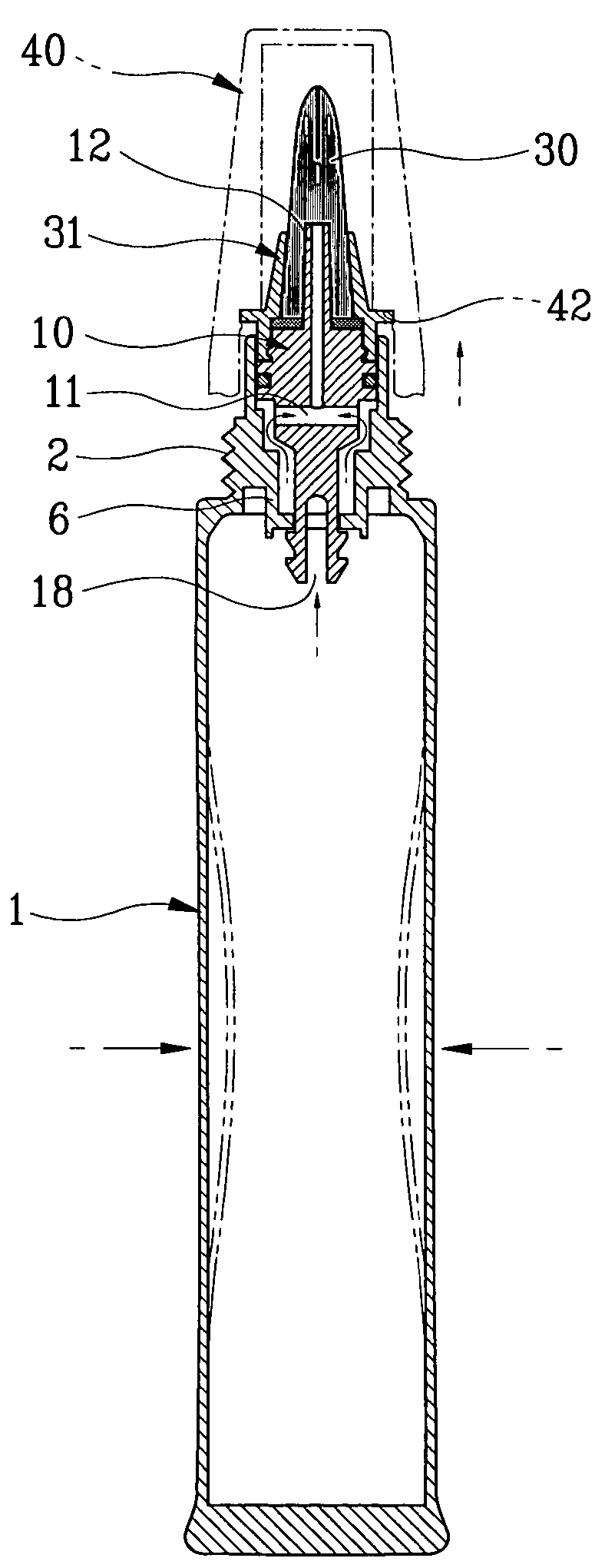
[0031]In the state where the cap 40 is thread-coupled with the tube-shaped container 1, as illustrated in FIG. 3, the pressing plate 31a of the supporting cap 31 to which the brush 30 is attached engaged with the upper side of the discharger 10 by the pressing step 42 formed at the inner circumference wall in the upper side of the cap 40 so that as the discharger 10 descends, the sla...

third embodiment

[0032]FIGS. 9 and 10 are sectional views illustrating a cosmetic case according to the present invention. By the male threads 2 of the upper outer circumferential wall of the tube-shaped container 1 of FIGS. 1 to 8, and by the outer protruding ring 2a of the tube-shaped container 1, and an inner protruding ring 41a of the cap 40, the cap 40 on the top of the tub-shaped container 1 can be forcibly opened without female treads 41 formed in the lower inner circumferential wall of the cap 40. Moreover, without the liquid guiding passage 11 formed in the center of the discharge hole 12, a vertical body 60 which is a vertical extension of the discharge hole 12, is formed. Corresponding to the structure of an upper step 61 formed in the upper side of the vertical body 60, a groove ring 62 is formed in the lower side of the outer circumferential wall of the vertical body 60 and several erected pieces 70 are formed in the upper inner circumferential wall of the tube-shaped container 1 to ope...


PUM


Abstract

A liquid cosmetic case adapted to dispense a cosmetic material which includes a tube-shaped container adapted to house a cosmetic material, said container being provided at one end thereof with threaded walls which define an aperture; a cap provided with locking slots and threads for screw engagement with the threaded walls of said container; a discharger disposed within said aperture, said discharger containing liquid guiding passages which communicate at one end with the container and at the other end with a conduit provided in such discharger; and a support cap engaged with the upper external portion of said discharger for securing a brush to the discharger conduit, said support cap containing locking flanges which engage with said locking slots provided in said cap, whereby upon the engagement and disengagement between the cap and the discharger, the communication through said liquid guiding passes between said container and said conduit in the discharger can be opened or closed.

Description

CROSS-REFERENCE TO RELATED APPLICATIONS[0001]This application claims the benefit of Korean Patent Applications No. 10-2004-0112884 and 10-2005-0094842, filed on Dec. 27, 2004 and Oct. 10, 2005, respectively in the Korean Intellectual Property Office, the disclosures of which are incorporated herein by reference.BACKGROUND[0002]1. Field of the Invention[0003]The present invention relates to a liquid cosmetic case in which a supporting cap to which a brush is fixed is attached to the upper side of a tube-shaped container that stores liquid cosmetic and is coupled with a discharger which is closed after discharging the liquid cosmetic. The cap is thread-coupled with the upper side of the tube-shaped container so that the discharger coupled with the supporting cap ascends and descends by opening and closing the cap. When the cap ascends, a ring-shaped step in the upper end of a liquid supplying container is opened so that a through hole and a liquid guiding passage formed by an inner pr...

Claims


Application Information

Patent Timeline
Patent Type & Authority Patents(United States)
IPC IPC(8): A46B17/04A46B11/04
CPCA45D34/042A46B11/0041A46B11/0079A46B11/0086A46B11/0089A46B2200/1046
Inventor BYUN, YOUNG KWANG
Owner BYUN YOUNG KWANG
Why Eureka
Try Eureka