
System for coloring a partially colored design in an alternating phase shift mask

a technology of alternating phase shift and mask, which is applied in the field of mask manufacturing, can solve the problems of phase coloring conflict, flattening of the hierarchy of the array, and virtually limitless combinations of such books

Inactive Publication Date: 2008-05-27
GLOBALFOUNDRIES INC
View PDF5 Cites 16 Cited by
  • Summary
  • Abstract
  • Description
  • Claims
  • Application Information

AI Technical Summary

Benefits of technology

The present invention provides an improved method for designing alternating phase shifting masks used in integrated circuit design. The method addresses issues of phase shape conflicts within the design layout and ensures that the phase shifting mask is designed in a way that avoids phase conflicts between adjacent cells. The method also includes rules for assigning phases to the phase shifting shapes, and automatically correcting any conflicts between the phases as the design progresses. The invention also provides a method for creating cell arrays with alternating phase shifting shapes that are colorable and comply with the coloring rules. The technical effects of the invention include improved design accuracy and efficiency in creating alternating phase shifting masks for integrated circuit design.

Problems solved by technology

The combinations of such books are virtually limitless.
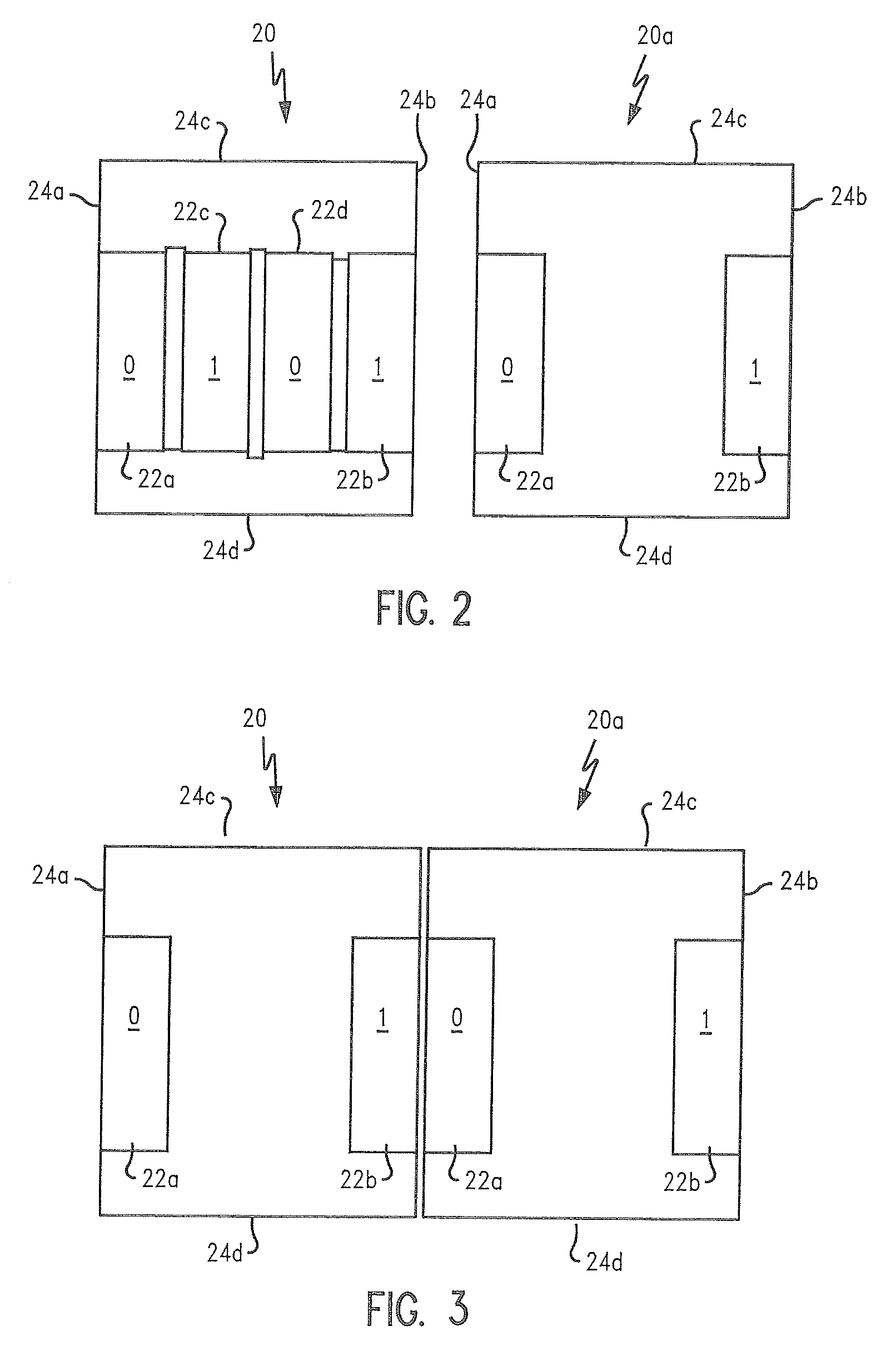
Because of potential for design rule violations when placing books next to each other, most standard cell libraries have fairly conservative rules about the positioning of phase shapes inside cell boundaries and sharing of phase shapes between adjacent cells.
Interaction of phase shapes between neighboring cells may cause phase coloring conflicts.
Additionally, when there are phase shape interactions between cells in an RLM, there are concerns about data volume and run time for altPSM generation in a mask design due to unrolling of phase shapes, resulting in the flattening of the hierarchy of the arrays built up from individual cells.
Further complications for altPSM mask design arise in the hierarchical construction of a full chip.
There is no current method to handle the phase coloring at the boundaries of such components automatically.

Method used


Image

  • System for coloring a partially colored design in an alternating phase shift mask
  • System for coloring a partially colored design in an alternating phase shift mask
  • System for coloring a partially colored design in an alternating phase shift mask

Examples


Embodiment Construction

[0045]In describing the preferred embodiment of the present invention, reference will be made herein to FIGS. 1-17 of the drawings in which like numerals refer to like features of the invention.

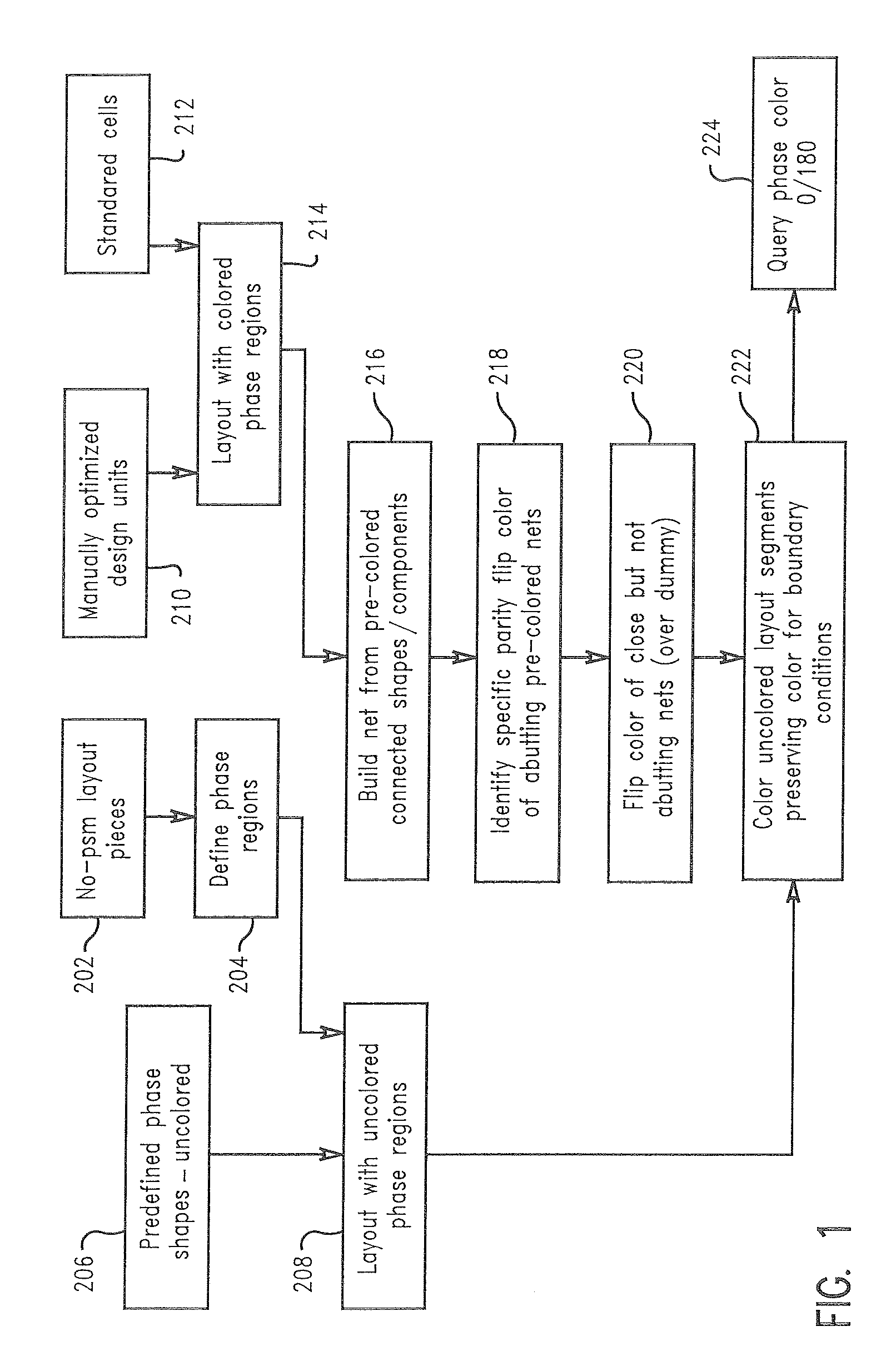
[0046]The present invention permits phase design and phase transmission assignments to be optionally made (i.e., pre-colored) within correctly colorable units of a hierarchical design, for example, at the book or small macro level (referred to as a cell), then in arrays of individual cells, which are assembled into nets, and the nets are further combined into arrays of nets and cells. Within each unit of the hierarchical design, e.g., cell, an array, a net, or array of nets and / or cells, the phase shapes are binary colorable. Stated another way, the assignment of phases or colors, when made within a hierarchical unit, will be correctly binary colored to satisfy the lithographic, manufacturability and other design rules, referred to collectively as coloring rules. The method of the present inv...


PUM

PropertyMeasurementUnit
phase shiftingaaaaaaaaaa
phaseaaaaaaaaaa
line widthsaaaaaaaaaa

Abstract

A method of designing an alternating phase shifting mask for projecting an image of an integrated circuit design. Phase units are binary colorable within each unit of the hierarchical circuit design, e.g., cell, an array, a net, or array of nets and / or cells, the phase shapes. The assignment of phases or colors within a hierarchical unit will be correctly binary colored to satisfy the lithographic, manufacturability and other design rules, referred to collectively as coloring rules. During assembly with other units, the coloring of phases in a hierarchical unit may change (e.g., be reversed or flipped), but the correct binary colorability of a hierarchical unit is preserved, which simplifies assembly of the integrated circuit layout.

Description

BACKGROUND OF INVENTION[0001]The present invention is directed to the manufacture of masks used in the lithographic production of integrated circuits and, in particular, to the manufacture of alternating phase shifting masks (altPSMs).[0002]As an alternative to chrome on glass (COG) masks used in the lithographic production of integrated circuits and other components, alternating phase shifting masks (altPSMs) have been employed in order to increase the resolution of the critical (active area) patterns projected. Such increased resolution enables smaller line widths to be exposed on the resist and consequently etched into or deposited on the wafer substrate. This is done by manipulating the electric field vector or phase of the energy beam, e.g., visible or ultraviolet light, used in the lithographic process. This phase variation is achieved in PSMs by modifying the length that a light beam travels through the mask material. By recessing the mask to an appropriate depth, light trave...

Claims


Application Information

Patent Timeline
Patent Type & Authority Patents(United States)
IPC IPC(8): G03F1/00G06F17/50
CPCG03F1/30
Inventor GRAUR, IOANAKIM, YOUNG O.LAVIN, MARK A.LIEBMANN, LARS W.
Owner GLOBALFOUNDRIES INC
Learn More