Method and apparatus using VAR measurements to control power input to a three-phase induction motor circuit

a three-phase induction motor and power input technology, applied in the direction of electric variable regulation, process and machine control, instruments, etc., can solve the problems of power being lost to the motor, wasting power, and affecting the operation of the circuit, so as to achieve the effect of facilitating circuit replacemen

Inactive Publication Date: 2008-05-27
ENVIRO WORLD SYST
View PDF31 Cites 66 Cited by
  • Summary
  • Abstract
  • Description
  • Claims
  • Application Information

AI Technical Summary

Problems solved by technology

It is well known that power is wasted when an alternating current (AC) induction motor is operated under a load below its rated load, or under a varying load.
The greater the VAR, the greater the loss of power in the system.
During that period of operation where the VA waveform takes on a negative value and lies below the X axis, there is a loss of power being sent to the motor.
In practice, in the case of a three phase system it has been found that the calculations required to be performed by the microprocessor is substantial, and thus the operational speed by which calculations can be conducted for each of the three input lines limits the frequency by which the solid state relays (SSRs) can be switched on and off.
In addition, the sum of the instantaneous current and voltage values in each of the three lines may vary, and thus inaccuracies in calculated values can result when these variations are not taken into account.

Method used


Image

  • Method and apparatus using VAR measurements to control power input to a three-phase induction motor circuit
  • Method and apparatus using VAR measurements to control power input to a three-phase induction motor circuit
  • Method and apparatus using VAR measurements to control power input to a three-phase induction motor circuit

Examples


Embodiment Construction

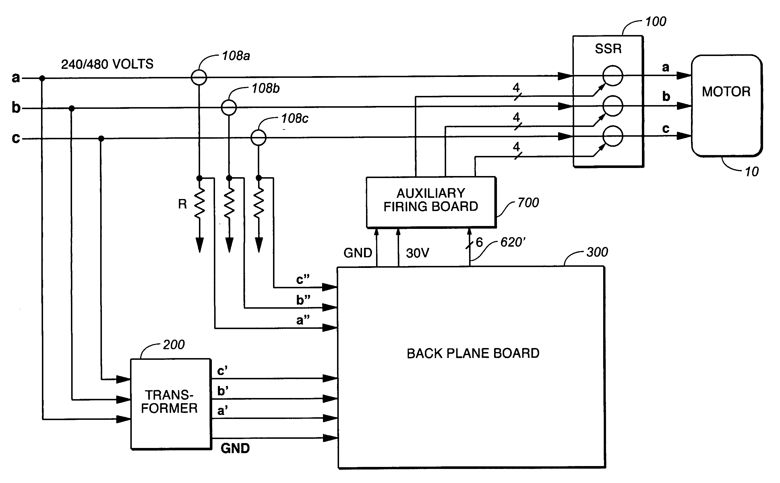
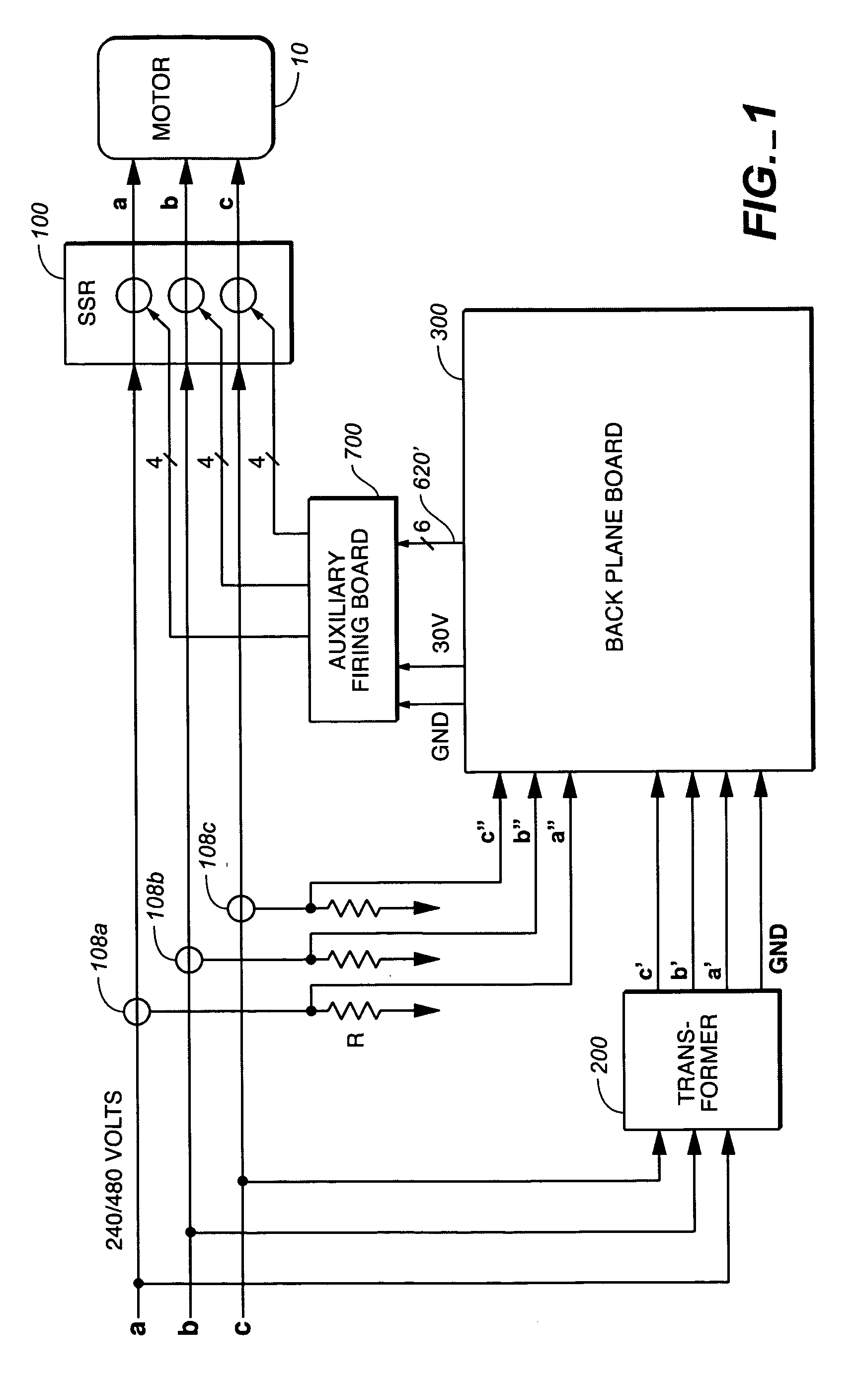
[0017]The operation of the system of the present invention and the arrangement of the circuits used herein will now be described with first reference to FIG. 1. Depicted therein is an incoming, three phase AC power source comprising three separate input power lines a, b, and c. The AC power in the lines is generally 120° out of phase between one line to the next, delivered from a power source at typical voltages of 240V or 480V. The power source is generally a power generation plant removed from the location of the motor 10 to be controlled. In one embodiment the power lines may connect to motor 10 through an intervening circuit breaker panel (not shown).

[0018]Input lines a, b, and c in turn are connected to the appropriate terminals of a three phase AC induction motor, to sequentially energize the motor windings which in turn drives the rotor of the motor. The operation of such three phase motors is well known in the art, and does not constitute a part of this invention. As such th...


PUM


Abstract

A method and apparatus are described for controlling the flow of power in each input line to a three phase AC inductive load in order to reduce the amount of VAR in the system, and thus increase the operational efficiency of the inductive load. Solid state relays are positioned in series in each of the three inductive load line inputs, and current allowed to flow to the inductive load only during the time during which the SSRs are in a conducting state. The calculation of VAR is achieved by processing data from each of the input lines using a separate controller boards each dedicated to each of the lines. The controller in turn, based on the calculated VAR, increments the time, either increasing or decreasing it from a predetermined value, during which the SSRs in that line remains in the non-conducting state.

Description

BACKGROUND OF THE INVENTION[0001]1. Field of the Invention[0002]This invention relates methods and apparatus for controlling the input to 3-phase alternating current (AC) induction motors. More particularly it relates to methods and apparatus for separately controlling the power being supplied through each of the three input lines to such a motor, using dedicated circuits to calculate the measure of reactive power and adjust the time during which solid state relays connected in series in each of the lines are maintained in a non-conducting state.[0003]2. Description of the Related Art[0004]It is well known that power is wasted when an alternating current (AC) induction motor is operated under a load below its rated load, or under a varying load. It is also well know that inherent in the operation of a three-phase alternating current induction motor is the presence of reactive power, expressed as voltamps reactive (VAR), the measure of VAR related to the operational inefficiency of t...

Claims


Application Information

Patent Timeline
Patent Type & Authority Patents(United States)
IPC IPC(8): G05F5/02
CPCH02J3/1892H02J3/26H02P23/0081H02P2207/01Y02E40/50H02P23/26
Inventor SIMPSON, III, HUGH CARDEN
Owner ENVIRO WORLD SYST
Why Eureka
Try Eureka