Rotation angle detection device having magnetic flux alteration unit

a detection device and magnetic flux technology, applied in galvano-magnetic devices, galvano-magnetic hall-effect devices, instruments, etc., can solve the problems of deteriorating absolute increasing costs, so as to improve detection accuracy of rotation angle detection devices, gentle magnetic flux variation at the top of the magnetic flux distribution, and improve the effect of detection accuracy

Inactive Publication Date: 2008-05-27
DENSO CORP
View PDF13 Cites 8 Cited by
  • Summary
  • Abstract
  • Description
  • Claims
  • Application Information

AI Technical Summary

Benefits of technology

[0014]In view of the above-described disadvantage, it is an object of the present invention to provide a rotation angle detection device, in which a distribution deviation of magnetic flux applied to a magnetism detection unit by a magnetic flux generation unit is restricted while a cost increase is suppressed.
[0015]According to an aspect of the present invention, a rotation angle detection device is provided with a magnetism detection unit, a magnetic flux generation unit for applying magnetic flux to the magnetism detection unit, and a magnetic flux alteration unit which is arranged at the magnetic flux generation unit. The magnetic flux generation unit is rotated relatively to the magnetism detection unit. A relative rotation angle between the magnetism detection unit and the magnetic flux generation unit is detected based on a density of the magnetic flux passing through the magnetism detection unit. The magnetic flux alteration unit alters a distribution of the magnetic flux which is applied to the magnetism detection unit by the magnetic flux generation unit, to restrict a deviation of the distribution of the magnetic flux.
[0016]Therefore, by only providing the magnetic flux alternation unit (e.g., magnetic flux abatement unit or magnetic flux augment unit) for the magnetic flux generation unit, the distribution deviation of the magnetic flux applied to the magnetism detection unit by the magnetic flux generation unit can be eliminated without altering members other than the magnetic flux generation unit and altering the arrangement position of the magnetic flux generation unit.

Problems solved by technology

Because the density of the magnetic flux applied to the magnetism detection unit J1 will significantly vary responding to the Z-axis-direction arrangement error, the absolute accuracy of the rotation angle detection device is deteriorated.
Therefore, the cost is greatly increased due to the specification variation.

Method used


Image

  • Rotation angle detection device having magnetic flux alteration unit
  • Rotation angle detection device having magnetic flux alteration unit
  • Rotation angle detection device having magnetic flux alteration unit

Examples


first embodiment

(First Embodiment)

[0032]A rotation angle detection device according to a first embodiment of the present invention will be described with reference to FIGS. 1A, 1B, 1C and 2. The rotation angle detection device is suitably used to detect, for example, a rotation angle (opening degree) of a throttle valve which is arranged at an air suction passage of an engine mounted at a vehicle.

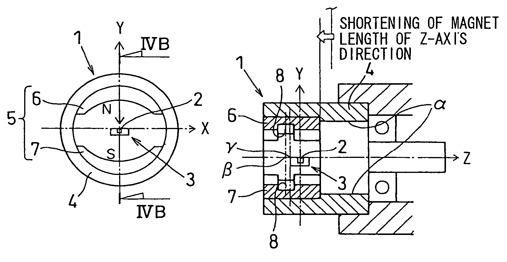
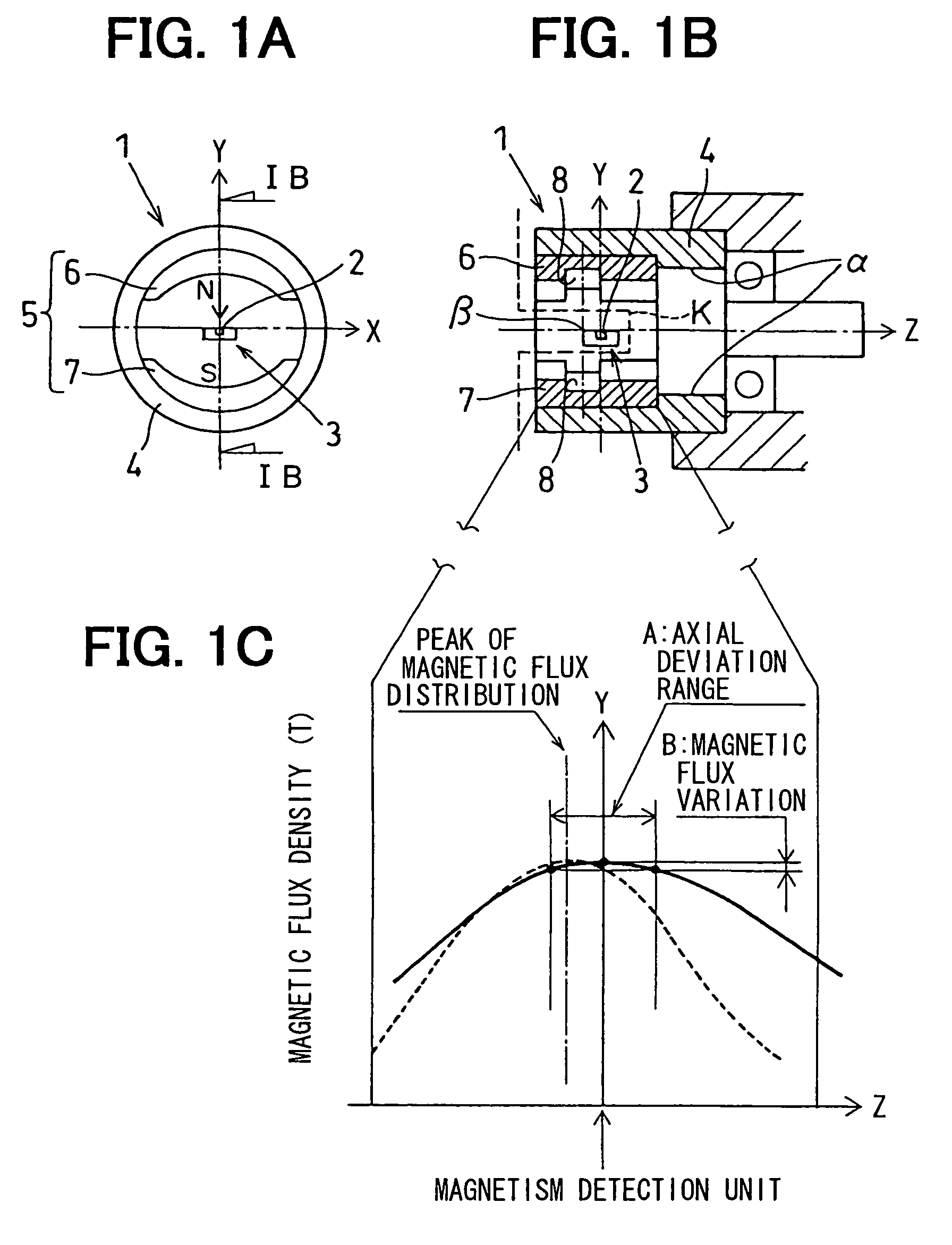
[0033]The rotation angle detection device includes a rotor 1 (rotation member) which is integrally rotated with a shaft of the throttle valve or the like, and a Hall IC 3 in which a magnetism detection unit 2 (e.g., Hall element) is embedded. The Hall IC 3 is supported by a fixed member K (non-rotation member) which is indicated by the broken line in FIG. 1B. The Hall element 2 is disposed at the rotation axis (Z-axis) of the rotor 1.

[0034]The rotor 1 is provided with a yoke 4 which is constructed of a substantially cylinder-shaped magnetic material, and a magnetic-flux generation unit 5 for emanating magn...

second embodiment

(Second Embodiment)

[0074]A second embodiment of the present invention will be described with reference to FIGS. 3A, 3B and 3C.

[0075]In the case where the radial-direction thickness of the magnet member 6, 7 is provided with the distribution which is even (constant) in the Z-axis direction throughout the magnet member 6, 7, the magnetic flux leaked to the surround from the Z-axis-direction end portions of the magnet member 6, 7 is large so that the magnetic flux strength at the Z-axis-direction center portion of the magnet member 6, 7 becomes relatively strong.

[0076]That is, the magnetic flux density distribution of the magnet members 6 and 7 has a substantial mountain shape. As a result, in the case where the arrangement position of the Hall element 2 deviates in the Z-axis direction, the density of the magnetic flux applied to the Hall element 2 significantly varies due to the magnetic flux density distribution having a substantially mountain-shaped incline.

[0077]According to the s...

third embodiment

(Third Embodiment)

[0080]A third embodiment of the present invention will be described with reference to FIGS. 4A, 4B and 4C.

[0081]Referring to FIGS. 4B and 4C, there exists the case where the Z-axis-direction center γ of the magnet member 6, 7 are arranged to deviate from the Hall element 2 (when being viewed in Y-axis direction) due to a design alteration of the rotation angle detection device, for example, a shortening of the Z-axis-direction length of the magnet member 6, 7. FIG. 4C shows the case where the Z-axis-direction center of the magnet member 6, 7 corresponds to the Hall element 2 when being viewed in the Y-axis direction. FIG. 4B shows the case where the Z-axis-direction center γ of the magnet member 6, 7 deviates from the Hall element 2 in the Z-axis direction. In this case, the distribution deviation of the magnetic flux exerted to the Hall element 2 will be further enlarged, due to both the magnetic flux leaking portion α and the Z-axis-direction deviation of the cen...


PUM


Abstract

A rotation angle detection device has a magnetism detection unit, a magnetic flux generation unit for applying magnetic flux to the magnetism detection unit, and a magnetic flux alteration unit provided for the magnetic flux generation unit. The magnetic flux generation unit is rotated relatively to the magnetism detection unit. A relative rotation angle between the magnetism detection unit and the magnetic flux generation unit is detected based on a density of the magnetic flux passing through the magnetism detection unit. The magnetic flux alteration unit alters a distribution of the magnetic flux generated by the magnetic flux generation unit, to compensate a deviation of the distribution of the magnetic flux.

Description

CROSS REFERENCE TO RELATED APPLICATION[0001]This application is based on a Japanese Patent Application No. 2005-5347 filed on Jan. 12, 2005, the disclosure of which is incorporated herein by reference.FIELD OF THE INVENTION[0002]The present invention relates to a rotation angle detection device for detecting a relative rotation angle between two members (e.g., rotation member and non-rotation member).BACKGROUND OF THE INVENTION[0003]Generally, referring to FIGS. 5A and 5B, a rotation angle detection device is provided with a magnetism detection unit J1 (e.g., Hall element embedded in Hall IC) disposed at a rotation axis (named Z-axis), a magnetic flux supply magnet J2 which has a semi-cylinder shape and applies magnetic flux to the magnetism detection unit J1, and a magnetic flux attraction magnet J3 which has a semi-cylinder shape and attracts the magnetic flux applied to the magnetism detection unit J1 by the magnetic flux supply magnet J2.[0004]The magnetic flux attraction magnet...

Claims


Application Information

Patent Timeline
Patent Type & Authority Patents(United States)
IPC IPC(8): G01B7/30
CPCG01D5/145
Inventor MIZUTANI, AKITOSHIBAN, TAKAO
Owner DENSO CORP
Why Eureka
Try Eureka