
Using a physical object to control an attribute of an interactive display application

a physical object and display application technology, applied in computing, instruments, electric digital data processing, etc., can solve the problems of not always easy, not always easy, and not always easy to use keyboards to get the computers to perform desired tasks, etc., to achieve convenient and intuitive adjustment of the effect of adjusting the execution of the application program

Inactive Publication Date: 2008-05-27
MICROSOFT TECH LICENSING LLC
View PDF3 Cites 35 Cited by
  • Summary
  • Abstract
  • Description
  • Claims
  • Application Information

AI Technical Summary

Benefits of technology

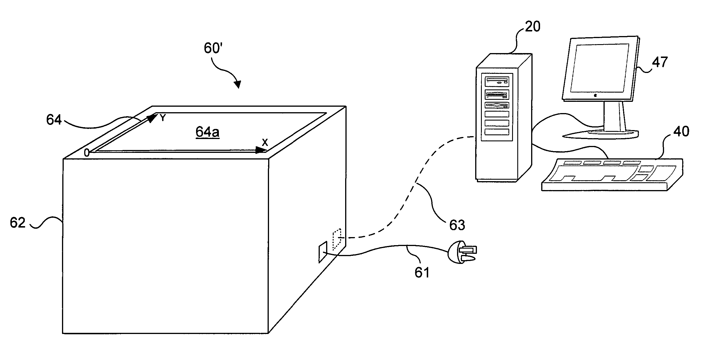
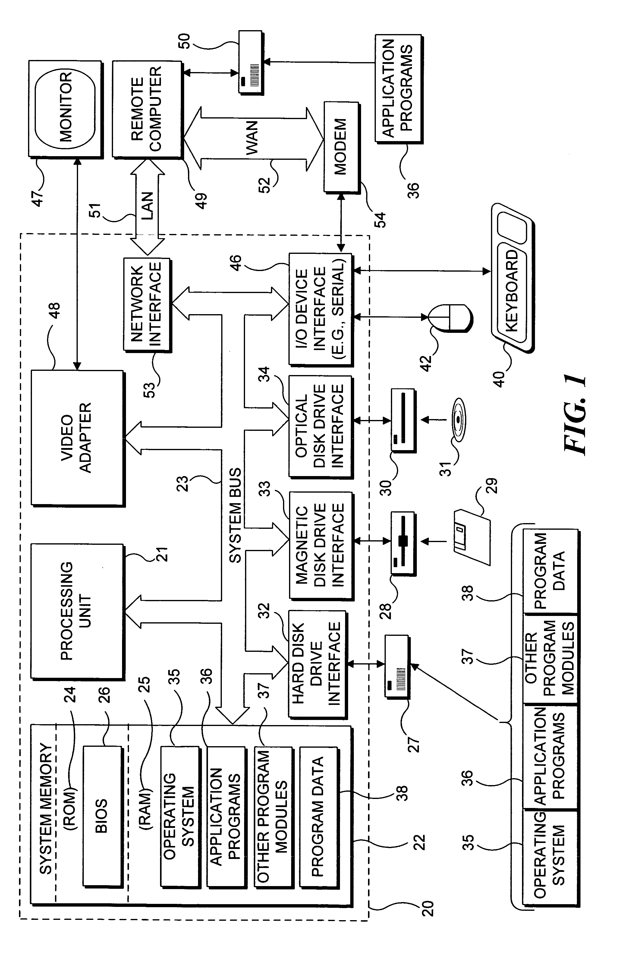
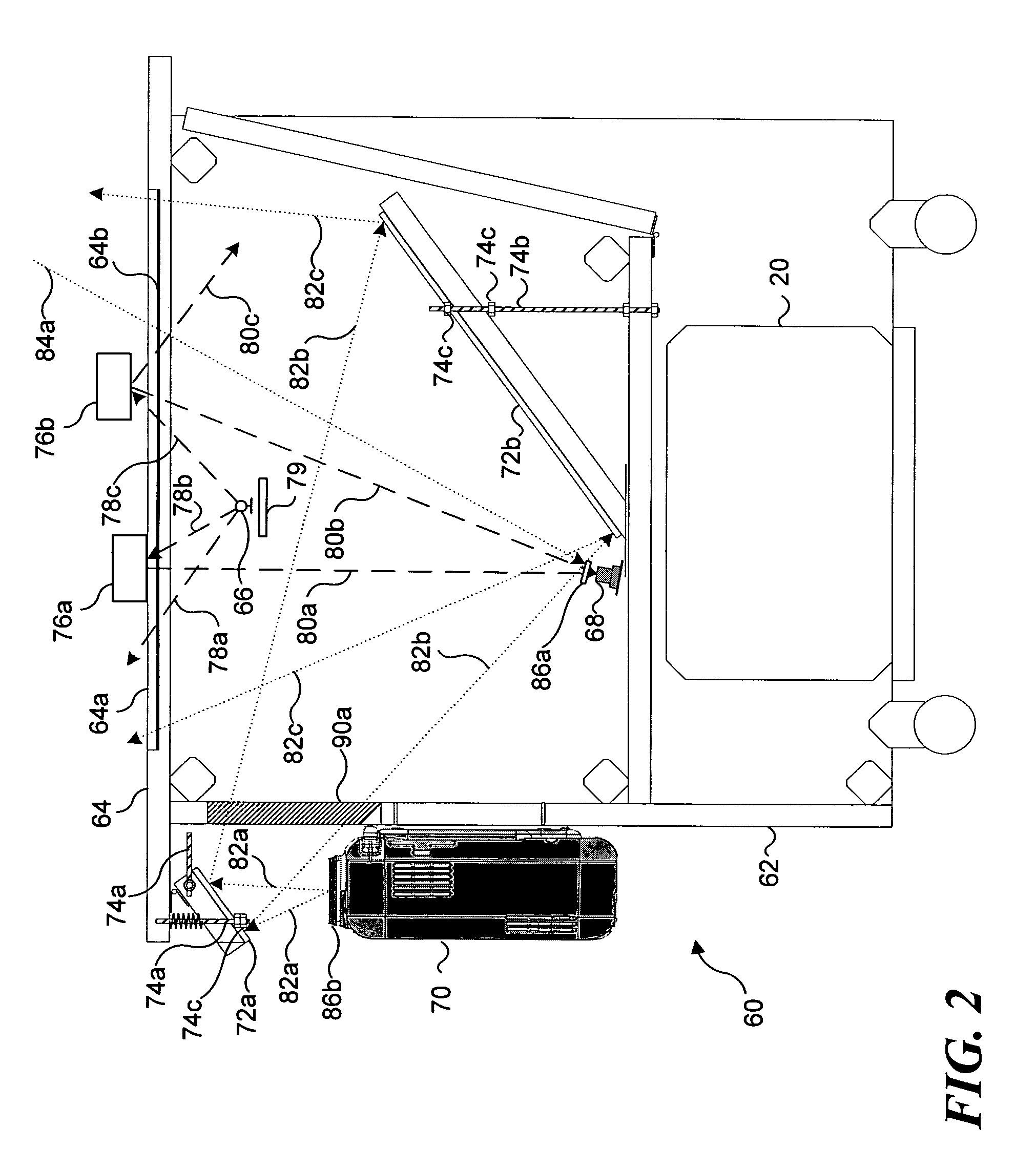
[0011]One of the advantages of the present invention is that it provides a convenient and intuitive way to control at least one attribute of a computer application executing on a computer system having an interactive display surface. An ordinary physical object may be placed on the interactive display surface. The associated computer system detects a position, shape, or other characteristic of the physical object and associates that characteristic with an attribute of the computer application. Manipulation of the physical object changes the characteristic perceived by the interactive display surface. Responding to the change in the characteristic, the computer system changes the attribute of the application program. Thus, a user can adjust the execution of the application program by placing an ordinary physical object on the interactive display surface and then manipulating the object.

Problems solved by technology

In hindsight, part of what is remarkable about the personal computer revolution is that the early personal computers were not very user friendly.
While personal computers were powerful tools, using keyboards to get the computers to perform desired tasks was not always straightforward, and certainly not always easy.
Saving the revised document also required similar, non-user friendly processes.

Method used


Image

  • Using a physical object to control an attribute of an interactive display application
  • Using a physical object to control an attribute of an interactive display application
  • Using a physical object to control an attribute of an interactive display application

Examples


illustration 950

[0101]Illustration 950 of FIG. 9B shows an alternative embodiment of an environment for generating audio signals based on sizes, shapes, and orientations of physical objects placed on interactive display surface 404. In the embodiment of illustration 950, the interactive display surface again includes a recording command area 952 having a rewind icon 954, a play icon 956, a pause icon 958, a stop icon 960, a record icon 962, and a fast forward icon 964.

[0102]A tone generation area 970 is divided into percussion region 974 and a melody region 976. A physical object may be placed in either of these two regions. In the illustrated example, a rectangular physical object 990 is placed in percussion region 974 and an irregular shaped physical object 992 is placed in melody region 976. A tone is generated using an arithmetic function that weights and combines values of the major and minor axes for ellipses representative of shapes 990 and 992, or a look-up table can be accessed, wherein th...


PUM


Abstract

An input to a computer system is made by manipulating a physical object disposed adjacent to an interactive display surface. An application having at least one changeable attribute is executed on the computer system. When the physical object is disposed adjacent to the interactive display surface, it is identified and its location is determined based upon a shape, a size, an infrared reflectance, or some other optical quality. The initial location and orientation of the physical object on the interactive display surface relative to the interactive display surface is identified. The attribute of the application is correlated with the physical object and is changed in response to movement of the physical object. The physical object can thus be used, for example, to select menu options and parameters within the application being executed.

Description

FIELD OF THE INVENTION[0001]The present invention generally pertains to a computing system having an interactive display surface operable to recognize objects in proximity to the interactive display surface, and, more specifically, to exploit the recognition capability of the interactive display surface to control applications executable on the computing system.BACKGROUND OF THE INVENTION[0002]It is well understood that the proliferation of personal computers has revolutionized the very nature of computing. The personal computer brought computers out of climate controlled data centers of large corporations and into small businesses and homes. Well before the Internet became widely available, people began using computers on a daily basis for activities ranging from accounting and tracking personal finances, to word processing, to games.[0003]In hindsight, part of what is remarkable about the personal computer revolution is that the early personal computers were not very user friendly...

Claims


Application Information

Patent Timeline
Patent Type & Authority Patents(United States)
IPC IPC(8): G09G5/08
CPCG06F3/017G06F3/0354G06F3/0425G06F3/048
Inventor DRUCKER, STEVEN M.WONG, CURTISROSEWAY, ASTADEHLIN, JOEL
Owner MICROSOFT TECH LICENSING LLC
Learn More