Method of conditioning a random field to have directionally varying anisotropic continuity

a random field and anisotropic continuity technology, applied in the field of multidimensional random field conditioning, can solve the problems of limiting the assumption of stationarity in geologic characteristics of all geostatistical algorithms, including spectral simulation, and the inability of geostatistical methods to allow the direction of continuity to vary spatially

Active Publication Date: 2008-05-27
EXXONMOBIL UPSTREAM RES CO
View PDF19 Cites 36 Cited by
  • Summary
  • Abstract
  • Description
  • Claims
  • Application Information

AI Technical Summary

Problems solved by technology

Nevertheless, all geostatistical algorithms, including spectral simulation, at present suffer from the limiting assumption of stationarity in the geologic characteristics of the modeled subsurface region.
A limitation of this method, however, is that it is well known in the art that the geologic characteristics of the subsurface are non-stationary.
Most geostatistical methods do not allow the direction of continuity to vary spatially, but instead impose the limitation of a single direction of maximum continuity on the model.
Very few geostatistical modeling methods have attempted to address this limitation.
This limits the ability to model locally rapid changes in continuity orientation.
In addition, the method is a variant of traditional geostatistical algorithms that use variograms and, as compared to spectral simulation, suffers from the limitations noted above.
However, the invention does not work well to condition rock-property continuity in geologic features or regions having more complex continuity patterns; i.e., features with continuity directions that cannot be defined by a single thalweg, such as a complex deltaic geometry.

Method used


Image

  • Method of conditioning a random field to have directionally varying anisotropic continuity
  • Method of conditioning a random field to have directionally varying anisotropic continuity
  • Method of conditioning a random field to have directionally varying anisotropic continuity

Examples


first embodiment

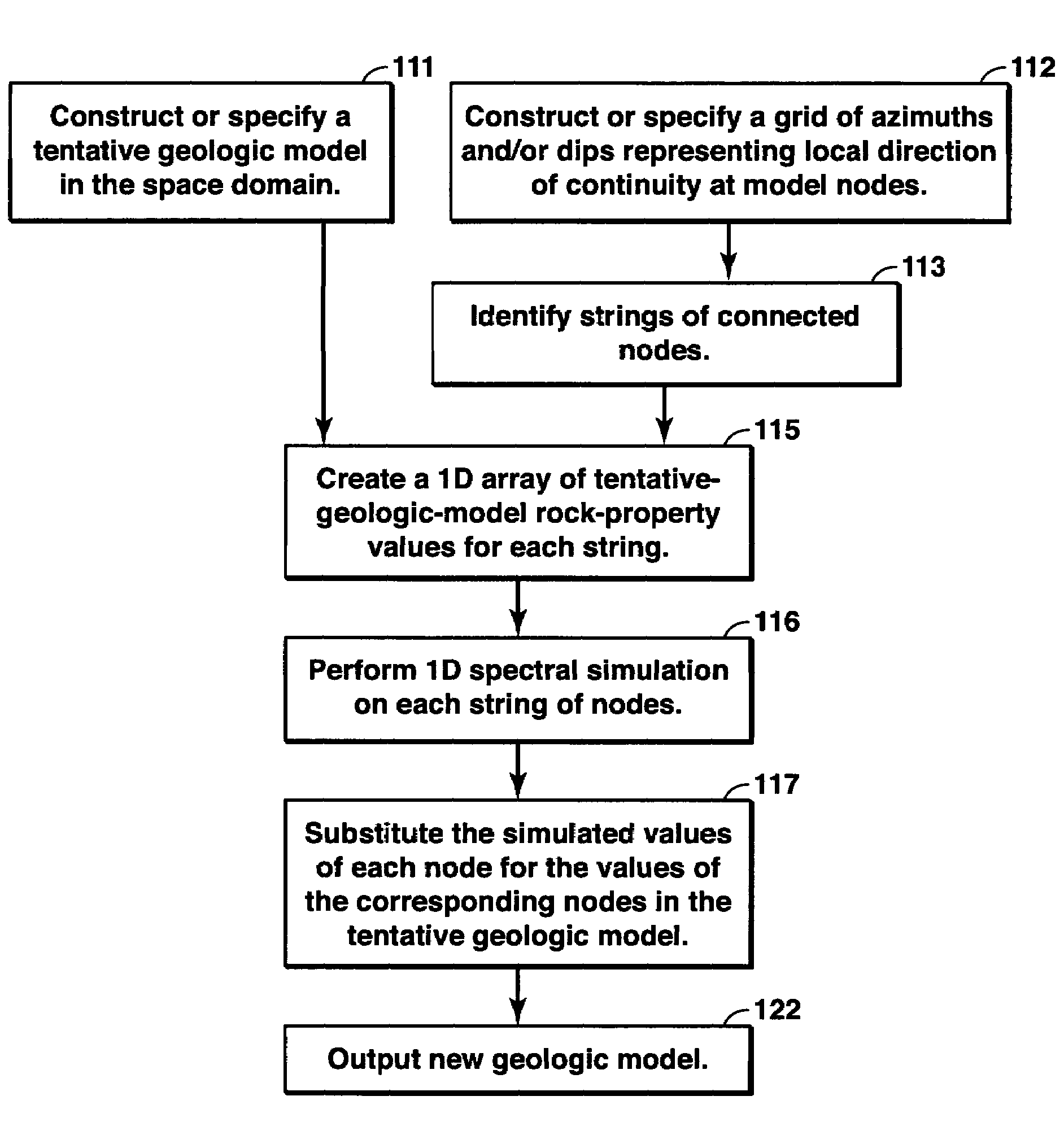
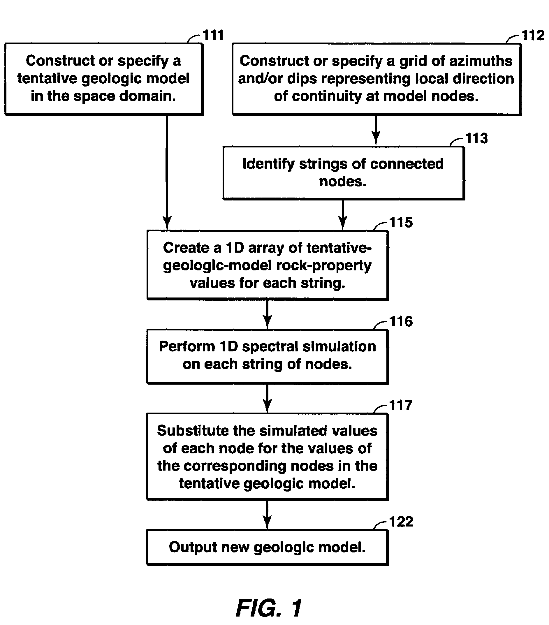
[0031]the present method is directed to the simulation of continuity in a single dimension; locally, that dimension is represented by the orientation of maximum continuity. For example, for a given tentative geologic model, it may be assumed that the local continuity variations that are present in a tentative model for all directions other than that represented by a single local azimuth and / or dip of interest are desirable and do not need to be modified. In such a case the present method is applied to simulate the model's rock properties in the single dimension, whether azimuthal or dip-oriented. FIG. 1 shows the steps for implementing this embodiment, as further described below.

[0032]First, using any practical means, a tentative, multi-dimensional geologic model, FIG. 1, step 111 is created. The tentative model is generated by assigning at least one rock property value to each block within the model's grid. This process will be well known to practitioners of geologic modeling, and ...

second embodiment

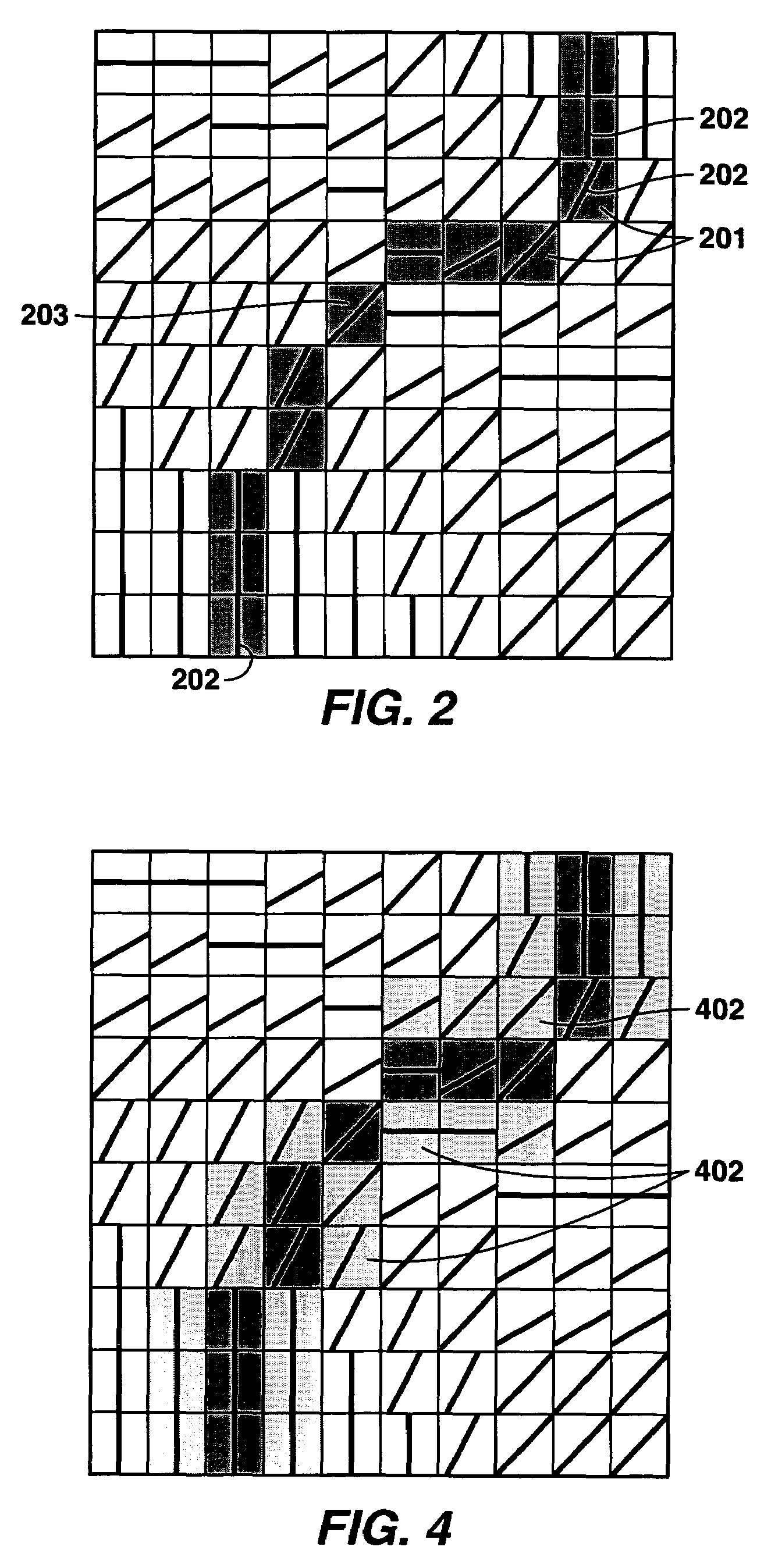
[0041]In a second embodiment, it may be desired to simulate spatial continuity in two or three dimensions; one of these dimensions represented by the orientation of maximum continuity. FIG. 3 depicts the steps of this embodiment, and FIG. 4 depicts an example representative layer of a geologic model for which this embodiment may be appropriate.

[0042]The first three steps of this embodiment, FIG. 3, steps 311, 312, and 313, are identical to steps 111, 112, and 113 in FIG. 1. In this embodiment, once the strings of nodes have been identified, FIG. 3, step 313, nodes are identified that neighbor each node in the identified strings, FIG. 3, step 314. As depicted in FIG. 4, the strings of neighboring nodes that are identified in FIG. 3, step 314 are the lighter-shaded blocks 402. Neighboring nodes may be defined as adjacent nodes that are perpendicular to the string node, though other definitions could also be applied. Neighboring nodes may surround the string nodes on all sides, for exa...

third embodiment

[0046]the present invention is described in the following paragraphs in the context of controlling the directional variation in continuity within each two-dimensional stratigraphic layer in a multi-layer geologic model. However, as will be understood to those skilled in the art, this embodiment may be employed to control two-dimensional directional variations in continuity occurring along any arbitrary plane of the model, or three-dimensional directional variations in continuity occurring within the geologic-model volume. In addition, the description of this embodiment focuses on the computationally less burdensome “string” simulation method (FIG. 1 above), although extension of this description to apply to the alternative “strip” simulation method (FIG. 3 above) is straightforward. FIG. 5 depicts the detailed steps that comprise this embodiment.

[0047]In this embodiment of the present invention, the tentative geologic model is constructed in four steps, FIG. 5, steps 511 through 514...


PUM


Abstract

The present invention is a method of generating a model of a random field which has directionally varying continuity. First, a tentative model for the random field is specified. Second, connected strings of nodes within the model are identified. Third, a spectral simulation on each of the strings of nodes is performed to determine updated values for the random field. Finally, the tentative model is updated with the data values from the spectral simulations.

Description

[0001]This application claims the benefit of U.S. Provisional Application No. 60 / 434,943 filed Dec. 19, 2002.FIELD OF THE INVENTION[0002]This invention relates to a method of conditioning a multi-dimensional random field. More specifically, this invention relates to a method of controlling the local direction of maximum rock-property continuity in a geologic model.BACKGROUND OF THE INVENTION[0003]Geologic models are commonly used in the petroleum exploration and production industry to characterize petroleum reservoirs and depositional basins. The term “geologic model” may represent either the entire volume of a subsurface volume of interest to an analyst, or a single region of interest within that larger subsurface volume. Geologic models are generally in the form of a three-dimensional array of blocks, sometimes referred to as cells. Furthermore, geologic modeling techniques frequently refer to nodes within a model; each such node generally falls at the center of any such block or ...

Claims


Application Information

Patent Timeline
Patent Type & Authority Patents(United States)
IPC IPC(8): G06G7/48G01V1/40G01V3/18G01V5/04G01V9/00G06F19/00G06G7/50G01V1/30G06FG06F7/48G06F7/60G06F17/50
CPCG01V1/301
Inventor CALVERT, CRAIG S.JONES, THOMAS A.BISHOP, GLEN W.YAO, TINGTINGFOREMAN, J. LINCOLNMA, YUAN
Owner EXXONMOBIL UPSTREAM RES CO
Why Eureka
Try Eureka