Rock bolt post grouting apparatus

a technology for installing apparatus and rock bolts, which is applied in the direction of anchoring bolts, earthwork drilling and mining, mining structures, etc., can solve the problems of obstructing the installation, reducing the grout encapsulation level of the bolt, and relatively ineffective resin cartridge chemical anchors

Inactive Publication Date: 2008-06-03
DYWIDAG SYST INT GMBH (DE)
View PDF15 Cites 37 Cited by
  • Summary
  • Abstract
  • Description
  • Claims
  • Application Information

AI Technical Summary

Benefits of technology

[0027]Preferably, a peripheral edge of said cap is adapted to engage a groove provided in said end fitting female component concavity to thereby retain the assembly of said plastic cap, said end fitting male component and said end fitting female component.

Problems solved by technology

In installations where larger diameter holes (typically 45 mm diameter) need to be drilled, resin cartridge chemical anchors are relatively ineffective as the large annulus between the conventional solid bolt (typically 22 mm diameter) and the hole wall is too large to enable effective mixing of the resin.
Firstly, when the rock bolt is installed into a roof covered with a wire mesh, the leading end of the plastic sleeve often catches on the wire, obstructing the installation.
Secondly, once the grouting nozzle is detached from the grouting chamber, grout drains from the grouting chamber under gravity through the hole into which the grouting nozzle had been inserted, thereby reducing the level of grout encapsulation of the bolt.
Thirdly, whilst the grout encapsulates the rock bolt within the rock bolt hole, the tail end of the rock bolt and the nut used to pre-tension the rock bolt remain exposed and subject to corrosion.
Further, if the rock face is uneven, the roof plate will often not be perpendicular to the hole and the rock bolt when pressed against the rock face by tensioning of the nut.
This causes the grouting chamber body, moving with the roof plate as a result of friction, to be misaligned with the nut.

Method used


Image

  • Rock bolt post grouting apparatus
  • Rock bolt post grouting apparatus
  • Rock bolt post grouting apparatus

Examples


Embodiment Construction

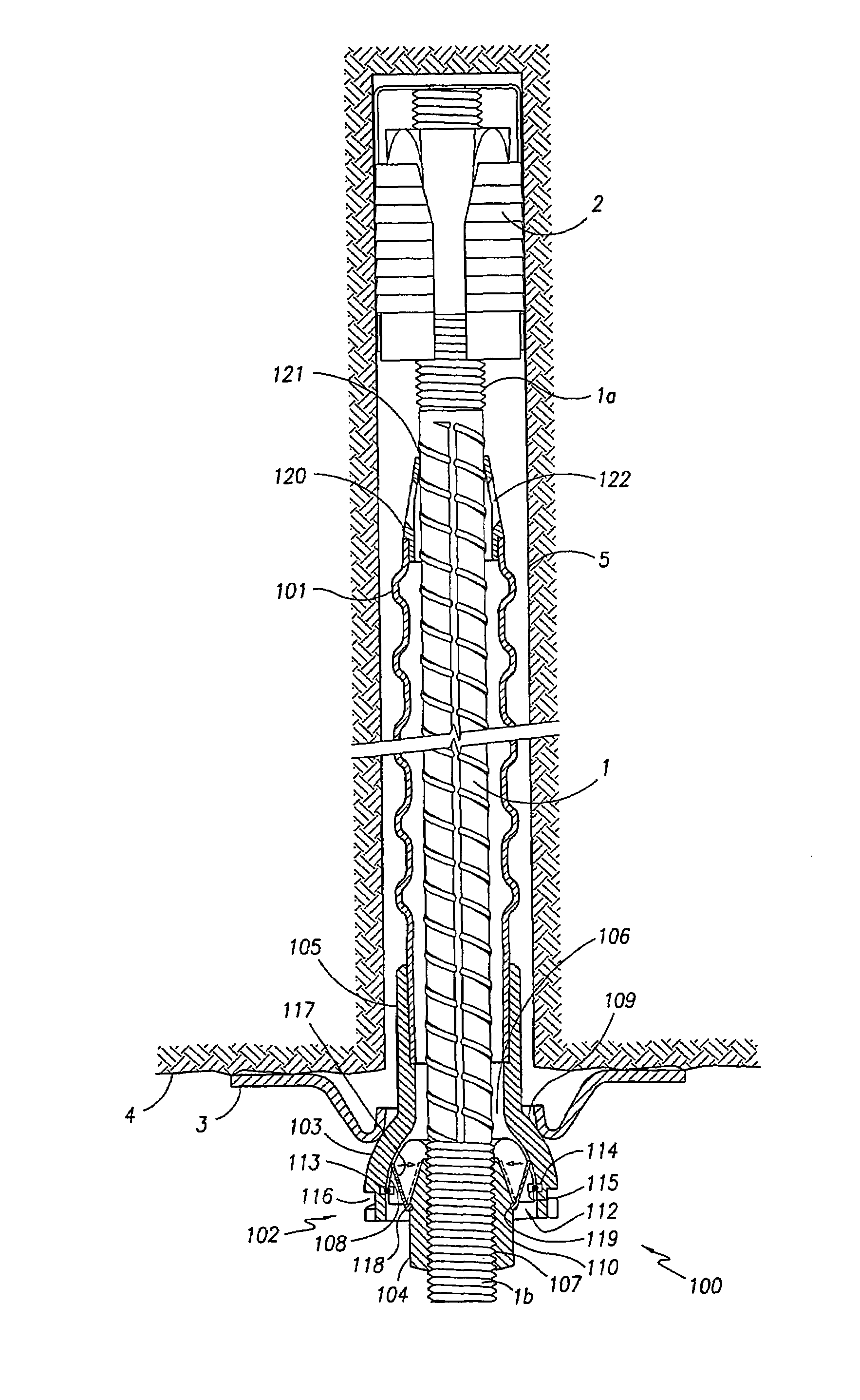
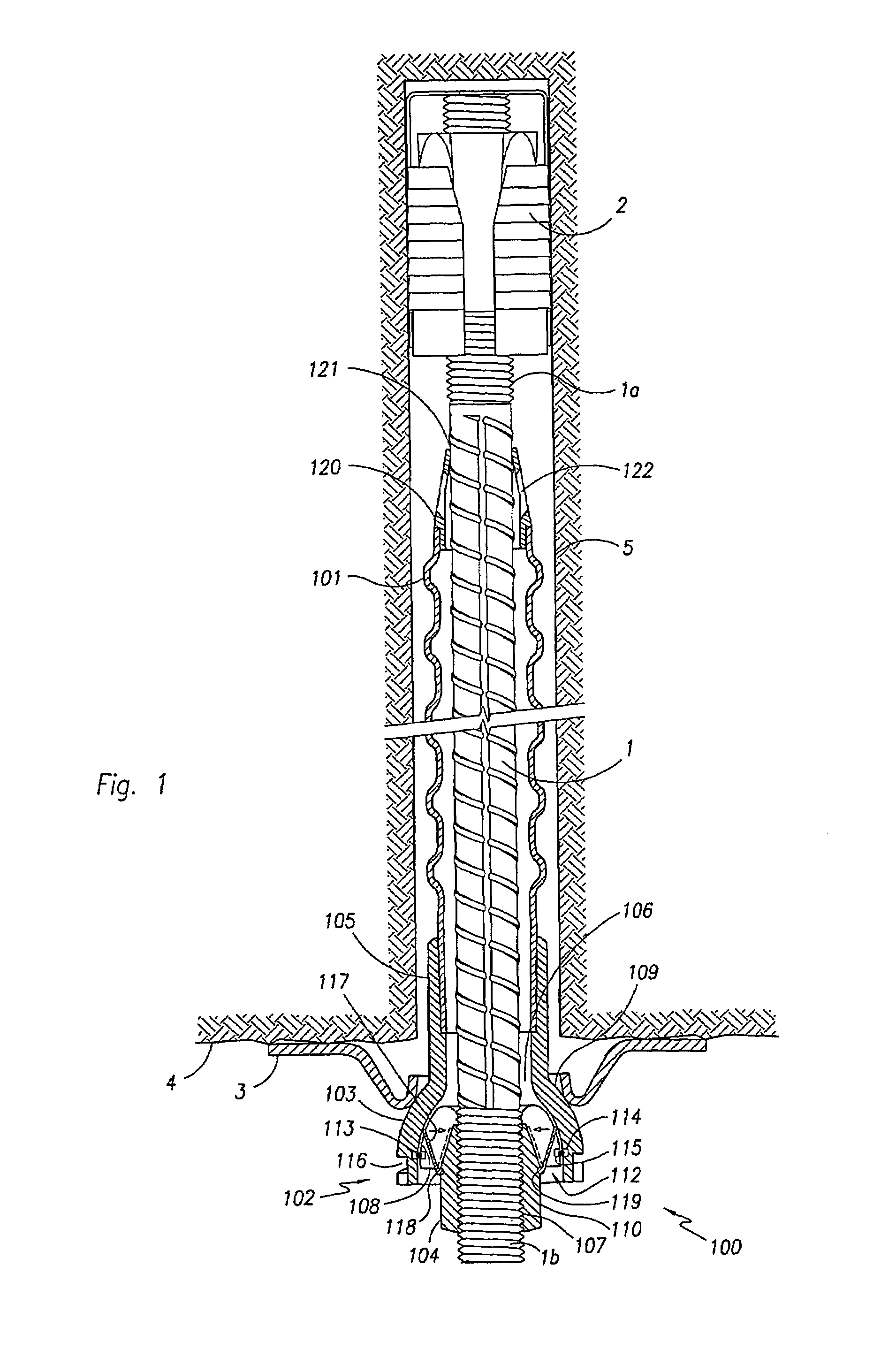
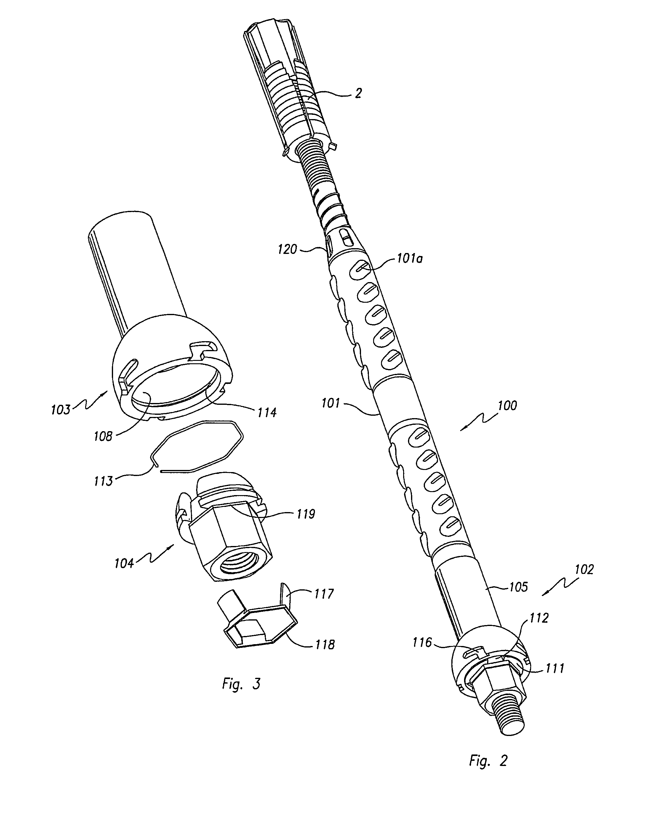
[0062]Referring to FIGS. 1 and 2 of the accompanying drawings, a rock bolt assembly consists of a standard rock bolt 1 having threaded first and second ends 1a, 1b, a standard expansion shell type mechanical anchor 2 threaded onto the rock bolt first end 1a and a rock bolt post-grouting apparatus 100. The post-grouting apparatus 100 has an elongate sleeve 101 and an end fitting 102. The elongate sleeve 101 is configured to is receive the rock bolt 1 with the rock bolt first end 1a extending beyond the sleeve first end 101a and the rock bolt second end 1b extending beyond the sleeve second end 101b. The sleeve 101 will typically have a length such that it extends from adjacent the expansion shell 2 at the rock bolt first end 1a to adjacent the threaded second end 1b of the rock bolt, being a length typically of the order of 2 m. The sleeve 101 will typically be formed of a plastics material and is provided with corrugations 101a which assist in anchoring the sleeve 101 with respect t...


PUM


Abstract

An apparatus (100) for post-grouting a rock bolt (1) has an elongate sleeve (101) adapted to receive a rock bolt (1) with a first end (1a) thereof extending beyond the sleeve first end (101a) and a second end (1b) thereof extending beyond the sleeve second end (101b). An end fitting (102) is attached to the sleeve second end (101b) and has a central aperture (106, 107) for receiving the rock bolt (1). Grout passages (112) communicate the exterior of the end fitting (102) with the interior of the sleeve (101). A seal means (117) is displaceable between open and closed positions so as to seal the grout passages (112). The seal means (117) is biased towards the closed position at which the grout passages (112) are substantially sealed. Injection of grout into the end fitting (102) via the passages (112) deflects the seal means (117) to the open position enabling flow of grout through the passages (112) and into the sleeve (101).

Description

TECHNICAL FIELD[0001]The present invention relates to improvements in rock reinforcement installations, and in particular relates to an apparatus for post-grouting of rock bolt installations to improve load transfer between the rock and the bolt and to provide corrosion protection.BACKGROUND OF THE INVENTION[0002]The roof of an underground mine is secured using rock bolts to confine the rock. The rock bolts are inserted into a hole, predrilled into the rock.[0003]Usually, the rock bolt is secured at the top of the hole by a mechanical or chemical anchor creating a point anchor. Alternatively, or additionally, the rock bolt is secured in the hole by grouting along its length with a cement or polyester resin.[0004]Grouting of the bolt along its entire length is the much preferred method to improve confinement of the rock through load transfer between the rock and bolt along its entire length rather than at a local area only. Grouting of the bolt also protects it from corrosion.[0005]I...

Claims


Application Information

Patent Timeline
Patent Type & Authority Patents(United States)
IPC IPC(8): E21D20/00E21D20/02E21D21/00
CPCE21D20/02E21D21/0033
Inventor RATAJ, MIECZYSLAW STANISLAWLANGWADT, OTMAR
Owner DYWIDAG SYST INT GMBH (DE)
Why Eureka
Try Eureka