
Knotless bioabsorbable suture anchor system and method

a bioabsorbable, anchor system technology, applied in the field of medical devices and procedures, can solve the problems of knot tying at the surgical site in closed surgical procedures, irritate tissue, and difficulty in time-consuming, and achieve the effect of reducing the amount of room for surgeons to perform the required manipulations at the surgical site, and reducing the risk of surgical complications

Inactive Publication Date: 2008-06-03
DEPUY MITEK INC
View PDF94 Cites 301 Cited by
  • Summary
  • Abstract
  • Description
  • Claims
  • Application Information

AI Technical Summary

Benefits of technology

"The present invention provides a knotless suture system for anchoring tissue to bone. The system includes a suture anchor, a suture needle, and two loops of suture thread. The suture anchor has a proximal end and a distal end with a bore formed therein. The system also includes an expander pin that is insertable into the bore of the anchor to cause it to radially expand. The system can securely attach detached tissue to bone without the need for tying a knot. The technical effects of the invention include improved ease of use, reduced surgery time, and improved tissue attachment."

Problems solved by technology

One problem encountered in the less invasive, closed surgical procedures is that the surgeon has significantly less room to perform the required manipulations at the surgical site.
Knot tying at the surgical site in closed surgical procedures, and even in open surgery, is difficult and time consuming due to inherent space constraints.
Further, knots and other bulky attachment means can irritate tissue over time.
Although generally useful, such systems can be limited to use only with certain types or shapes of tissue, or to use with certain anatomical structures.
While useful, the suture anchor and system disclosed in this patent is not believed to be absorbable.
This is undesirable because it unnecessarily irritates the injured tissue and it requires opening a much larger hole in the tissue.

Method used


Image

  • Knotless bioabsorbable suture anchor system and method
  • Knotless bioabsorbable suture anchor system and method
  • Knotless bioabsorbable suture anchor system and method

Examples


Embodiment Construction

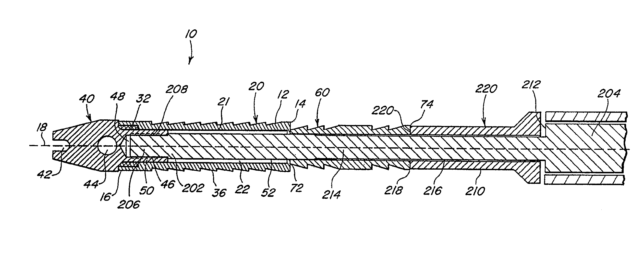
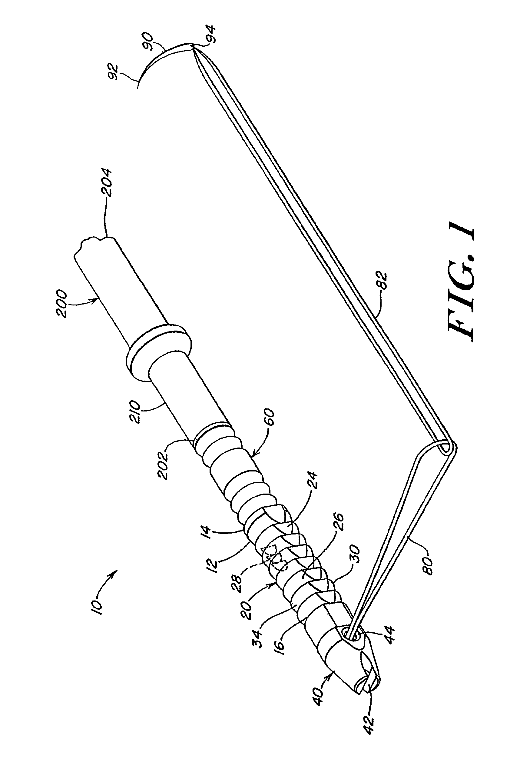
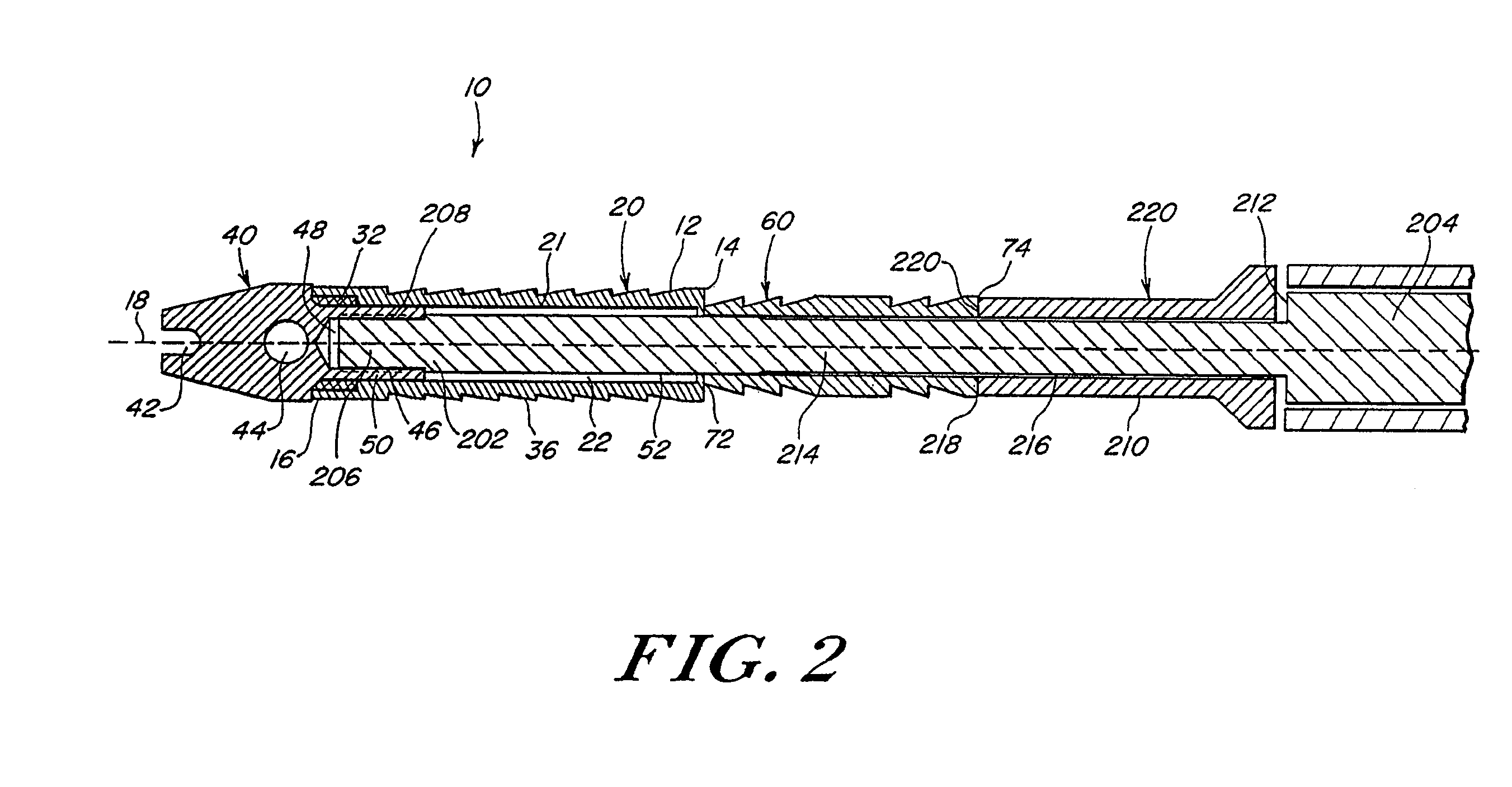
[0036]Referring now to FIGS. 1 through 2A, a system for anchoring tissue to bone in accordance with the invention is shown. The system 10 includes a suture anchor 12 configured to radially expand into bone. The suture anchor 12 has a proximal end 14 and a distal end 16 having a bore 22 that extends along a longitudinal axis 18 thereof. The suture anchor 10 includes a suture-engaging tip 40 at the proximal end 14 and a separate, radially expandable sleeve 20 at the distal end 16. The system of FIG. 1 also includes a first suture loop 80 attached to the suture-engaging tip 40, a suture needle 90, and a second suture loop 82 attached to the suture needle 90. The first suture loop 80 and second suture loop 82 are interlocked with each other. The system also includes an expander pin 60 that is configured and sized for insertion into the bore 22 of the expandable sleeve 20, causing the suture anchor 10 to radially expand from a first diameter to a second diameter.

[0037]The sleeve 20 is at...


PUM


Abstract

A knotless suture system for anchoring tissue to bone is provided. The system includes a suture anchor configured to radially expand into bone. The suture anchor has a proximal end and a distal end with a bore formed therein. The system further includes a first loop of suture thread attached to the distal end of the suture anchor, a suture needle, and a second loop of suture thread attached to the needle and interlocked with the first loop of suture thread. The system also includes an expander pin that is configured and sized for insertion into the bore of the suture anchor, causing the anchor to radially expand from a first outer diameter to a second outer diameter. A method is also provided by which a detached tissue may be securely attached to bone in an anatomically correct position without the need to tie a knot.

Description

CROSS-REFERENCE TO RELATED APPLICATIONS[0001]This application is a continuation of application Ser. No. 09 / 691,685 filed Oct. 18, 2000 now U.S. Pat. No. 6,641,596, titled “Knotless Bioasorbable Suture Anchor System And Method,” which is hereby incorporated by reference in its entirety.STATEMENT REGARDING FEDERALLY SPONSORED RESEARCH[0002]Not Applicable.FIELD OF THE INVENTION[0003]The invention relates generally to medical devices and procedures. More particularly, this invention relates to a knotless bioabsorbable suture anchor system for attaching soft tissue to bone, and to methods for attaching soft tissue to bone.BACKGROUND OF THE INVENTION[0004]Soft tissues, such as ligaments, tendons and muscles, are attached to a large portion of the human skeleton. In particular, many ligaments and tendons are attached to the bones which form joints, such as shoulder and knee joints. A variety of injuries and conditions require attachment or reattachment of a soft tissue to bone. For example...

Claims


Application Information

Patent Timeline
Patent Type & Authority Patents(United States)
IPC IPC(8): A61B17/04A61B17/00A61B17/06A61B17/56A61F2/08
CPCA61B17/0401A61F2/0811A61B2017/00004A61B2017/00862A61B2017/0406A61B2017/0409A61B2017/0412A61B2017/0414A61B2017/0424A61B2017/0427A61B2017/0432A61B2017/0438A61B2017/0454A61B2017/0458A61F2/0805A61F2002/0835A61F2002/0888Y10S606/908Y10S606/91
Inventor LIZARDI, JOSE E.
Owner DEPUY MITEK INC
Learn More