Tuned frequency portal for power transfer in MRI environment

a technology of tuning frequency and environment, which is applied in the direction of using reradiation, instruments, diagnostic recording/measuring, etc., can solve the problems of impracticality, bulky air core transformers, and inefficient air core transformers, so as to avoid the blocking effect of the tuned circuit, transfer and isolate

Inactive Publication Date: 2008-06-03
INVIVO CORP
View PDF10 Cites 6 Cited by
  • Summary
  • Abstract
  • Description
  • Claims
  • Application Information

AI Technical Summary

Benefits of technology

[0007]The present inventors have recognized that power can be effectively transferred and isolated in an MRI environment by the dielectric of high voltage but small capacitance capacitors forming part of a tuned circuit blocking the normal frequency (60 Hertz) of line current. This simple approach does not require complex conversions from one type of power to another and uses a low cost circuit design. The transferred power is shifted in frequency to avoid the blocking effect of the tuned circuit.
[0008]Unlike an air core transformer approach, the present invention produces very little radiated electrical power such as may interfere with the MM machine and the circuit may be compact. Isolation is provided in two directions limiting power to the patient and limiting power to the equipment.

Problems solved by technology

The MRI machine is a difficult environment for other electrical instrumentation.
The switched magnetic gradients and the RF pulse create electromagnetic interference and the MRI receiving antenna is sensitive to interference from other devices.
Conventional iron-core transformers can provide such isolation, but are impractical in the MRI environment because of their ferromagnetic cores.
Air core transformers, such as provide adjacent windings of copper conductors without a ferromagnetic core, may be used; however, air core transformers are bulky and inefficient, and this latter drawback generates heat that can be a problem in a patient contacting device.
The conversion process provides inherent limitations in power transfer.
This approach requires complex mechanisms and is practically limited to extremely low power transfer.

Method used


Image

  • Tuned frequency portal for power transfer in MRI environment
  • Tuned frequency portal for power transfer in MRI environment

Examples


Embodiment Construction

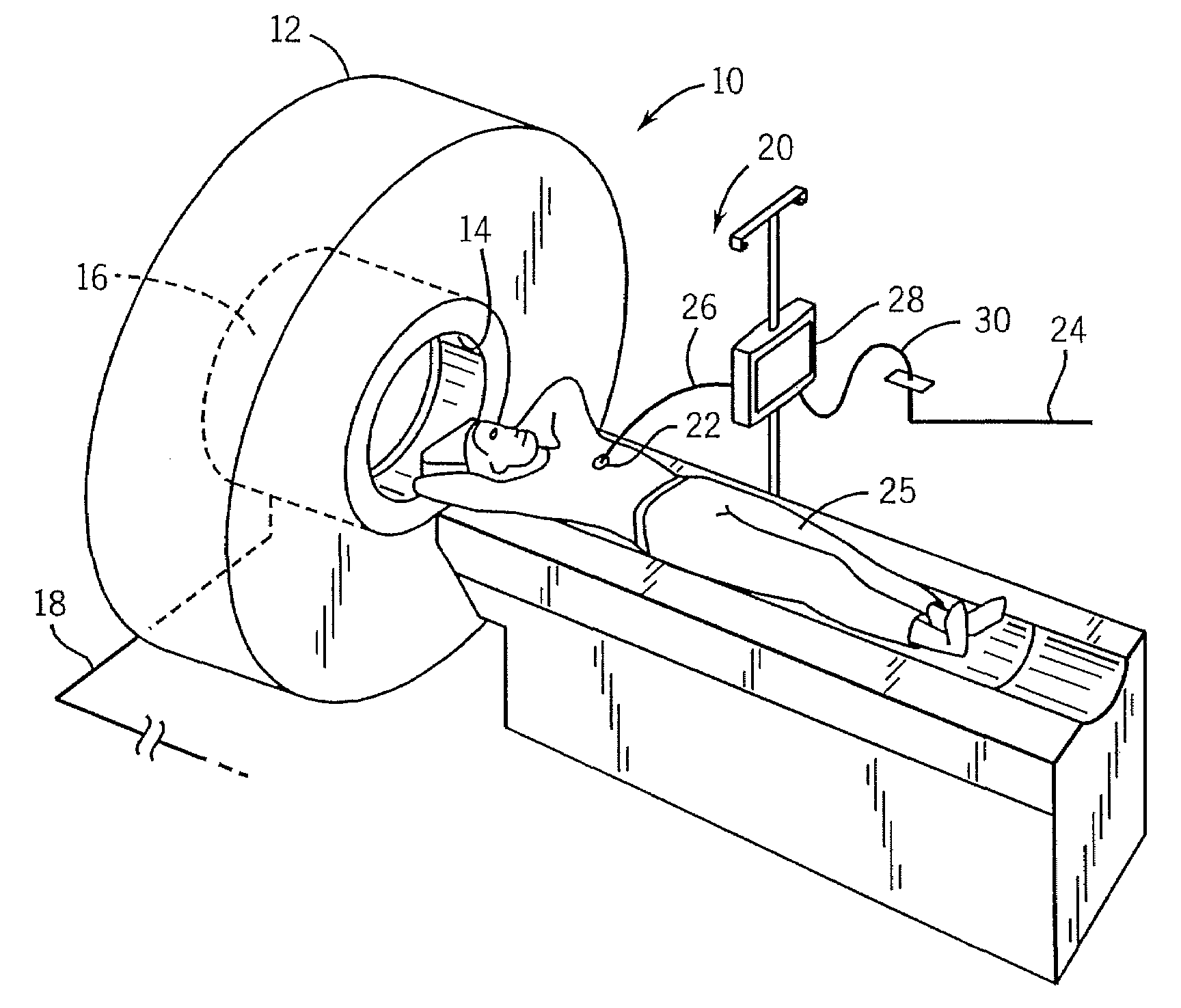
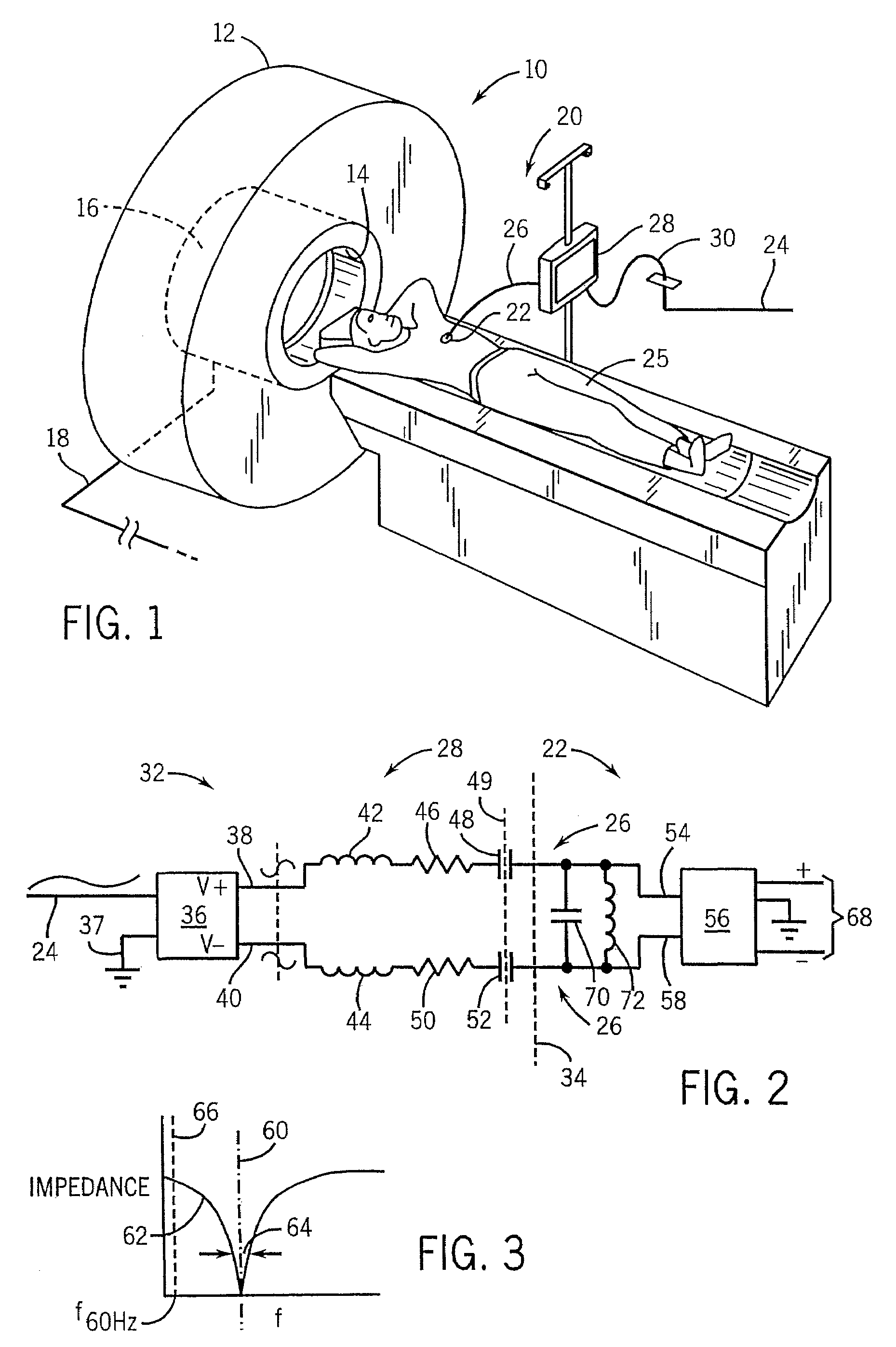
[0041]Referring now to FIG. 1, an MRI machine 10 may include a polarizing magnet 12, for example, that creates a strong polarizing magnetic field. The polarizing magnetic field is such as to saturate ferrites and prevent the use of ferromagnetic materials in the region of the MRI machine 10.

[0042]The polarizing magnet 12 may include a bore 14 into which the patient 25 may be placed for scanning. Within the bore 14, the patient 25 is surrounded by a coil set 16 providing for an RF excitation pulse, one or more gradient magnetic fields, and an antenna for detecting a faint NMR signal, as will be understood to those of ordinary skill in the art. The coil set 16 communicates with remote analysis signal processing electronics and computers (not shown) via cables 18.

[0043]The present invention provides a patient monitoring system 20 having an on-patient sensor unit 22 requiring a source of electrical power. The on-patient sensor unit 22 may, for example, include transducers for detecting ...


PUM


Abstract

A circuit for isolating line voltage from a patient in an MRI environment, uses a filter network tuned to line voltage and incorporating blocking capacitors to eliminate the need for bulky air core transformers, complex energy transfer systems, and ferromagnetic components, while providing reduced heating such as might produce patient discomfort.

Description

CROSS-REFERENCE TO RELATED APPLICATIONSSTATEMENT REGARDING FEDERALLY SPONSORED RESEARCH OR DEVELOPMENTBACKGROUND OF THE INVENTION[0001]The present invention relates generally to magnetic resonance imaging (MRI) equipment and in particular to a method of providing electrically isolated power to patient monitoring equipment used in conjunction with MRI.[0002]Magnetic resonance imaging can provide sophisticated images of the human body by detecting faint nuclear magnetic resonance (NMR) signals primarily from concentrations of hydrogen protons. In MRI, the patient is located in a strong polarizing magnetic field and hydrogen protons of the patient's tissues are excited into precession with a strong radio frequency (RF) pulse. A series of applied gradient magnetic fields are switched on and off to spatially encode the protons by phase and frequency after which sensitive antennas are used to detect the NMR signals which can then be reconstructed into images.[0003]The MRI machine is a dif...

Claims


Application Information

Patent Timeline
Patent Type & Authority Patents(United States)
IPC IPC(8): G01V3/00
CPCA61B5/055
Inventor FISHER, STEPHEN DOUGLASHARWELL, ROBERT ANDREW
Owner INVIVO CORP
Why Eureka
Try Eureka