
Image compression method and device

An image compression and image technology, applied in the field of image processing, can solve problems such as incompatible compression distortion

Active Publication Date: 2019-08-09
SHENZHEN CHINA STAR OPTOELECTRONICS TECH CO LTD
View PDF4 Cites 2 Cited by
  • Summary
  • Abstract
  • Description
  • Claims
  • Application Information

AI Technical Summary

Problems solved by technology

[0003] The purpose of this application is to provide an image compression method and device to solve the block effect caused by image compression, and to improve the compression distortion caused by the use of a mapping matrix in the prior art that cannot be compatible with multiple quantization coefficients

Method used


Image

  • Image compression method and device
  • Image compression method and device
  • Image compression method and device

Examples


Embodiment Construction

[0050] In order to make the purpose, technical solution and effect of the present application more clear and definite, the present application will be further described in detail below with reference to the accompanying drawings and examples. It should be understood that the specific embodiments described here are only used to explain the present application, and the word "embodiment" used in the description of the present application is intended to be used as an example, illustration or illustration, and is not intended to limit the present application.

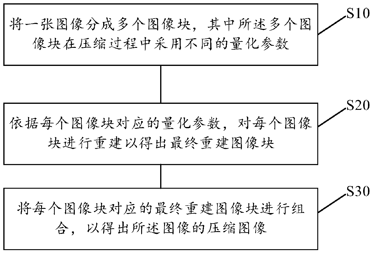
[0051] see figure 1 , the image compression method of the present application comprises the following steps:

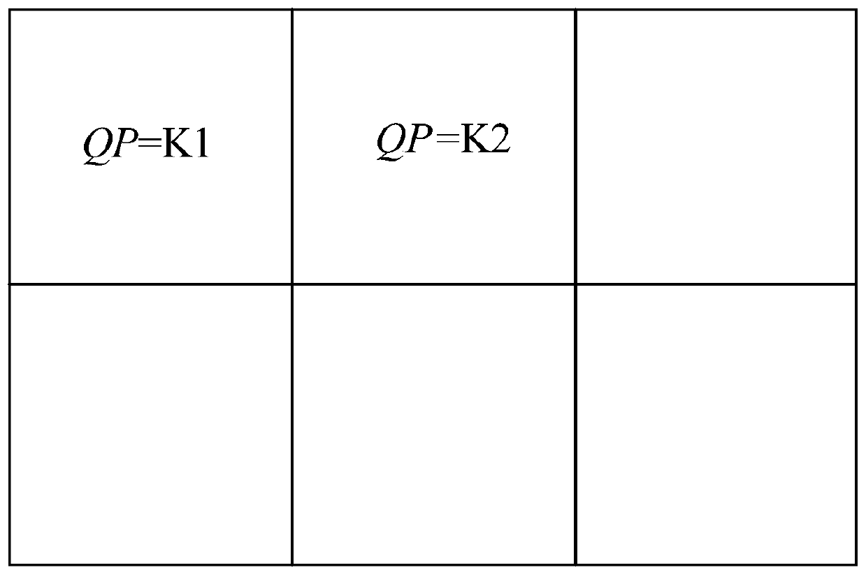
[0052] Step S10—dividing an image into multiple image blocks, wherein the multiple image blocks use different quantization parameters during the compression process;

[0053]Step S20—reconstructing each image block according to a quantization parameter (quantization parameter, QP) corresponding to each image block ...


PUM


Abstract

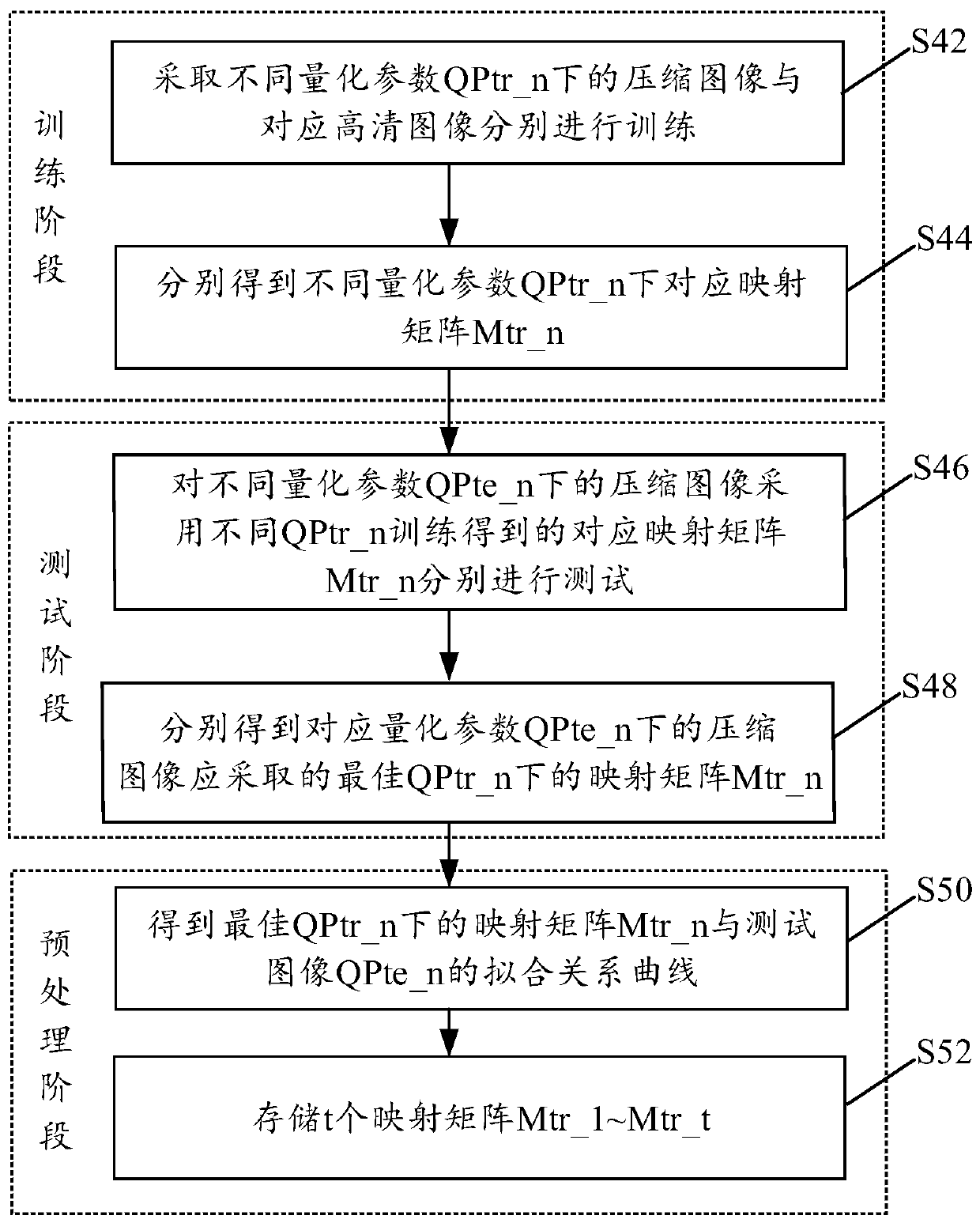
According to the invention, image blocks are respectively reconstructed in a blocking manner; in the reconstruction process of each image block; two most adjacent mapping matrixes are solved accordingto the size of the quantization parameter in the image block; the two mapping matrixes are used for reconstructing the image blocks to obtain two reconstructed image blocks, the two reconstructed image blocks are fused in a linear interpolation mode to obtain final reconstructed image blocks, and all the final reconstructed image blocks are combined to obtain a final reconstructed image. According to the method, the block effect caused by image compression is solved, and the situation of compression distortion caused by the fact that one mapping matrix is adopted and cannot be compatible withmultiple quantization coefficients in the prior art is improved.

Description

technical field [0001] The present application relates to an image processing technology, in particular to an image compression method and device. Background technique [0002] Block discrete cosine transform (block discrete cosine transform, BDCT) is widely used in image compression coding such as JPEG, H.264 / AVC and H.265 / HEVC. This image is coded for compression and often quantized after transformation. However, this coding technique often produces blocking artifacts due to separate transforms for each image block and coarse quantization. In order to ensure image quality, each image block in a frame of image adopts a different quantization parameter (quantization parameter, QP). Sparse representation can be used to reduce the block effect, but the traditional sparse representation training model is only suitable for one quantization parameter. When the quantization parameter is other values, the processed image cannot get the best effect. Contents of the invention ...

Claims


Application Information

Patent Timeline
IPC IPC(8): H04N19/167H04N19/17H04N19/423H04N19/139H04N19/126
CPCH04N19/126H04N19/139H04N19/167H04N19/17H04N19/423
Inventor 陈云娜
Owner SHENZHEN CHINA STAR OPTOELECTRONICS TECH CO LTD
Learn More