Differential and quadrature harmonic VCO and methods therefor

a harmonic and differential technology, applied in the field of voltage control oscillators, can solve the problems of complex structure of transmitter and receiver, complex transmitter and receiver, and own drawbacks, and achieve the effects of simple structure, improved rf voltage, and improved tuning rang

Inactive Publication Date: 2008-06-03
SAMSUNG ELECTRONICS CO LTD
View PDF11 Cites 12 Cited by
  • Summary
  • Abstract
  • Description
  • Claims
  • Application Information

AI Technical Summary

Benefits of technology

[0016]It is still another aspect of the present invention to provide a voltage controlled oscillator with an improved tuning range and a simple structure.

Problems solved by technology

These methods, however, not only have their own drawbacks and limits, but also make the transmitter and receiver more complicated than necessary.
Meanwhile, the divide-by-four circuit makes the structure of a transmitter and receiver more complicated.
The conventional coupled oscillator also has many shortcomings, such as, its output power is not sufficient for a highest dynamic frequency or it has a very complicated coupled structure.
Another defect of the disclosure is that because the circuits are organized in a ring oscillator building block, without an additional circuit, sufficient RF outputs and satisfactory noise performance can not be obtained.
However, this type of circuit can only be used as a quadrature generator, and is not appropriate for a harmonic generator.
This type of circuit may be effectively used with a quadrature oscillator for a wide-band receiver system, but is not appropriate for the harmonic generator.
However, neither simulation nor measurement data is given, and there is no way to find out signal magnitude and a maximum system frequency (speed).
The disclosed coupling method is effective for generating quadrature phase signals, but cannot generate differential phase signals.

Method used


Image

  • Differential and quadrature harmonic VCO and methods therefor
  • Differential and quadrature harmonic VCO and methods therefor
  • Differential and quadrature harmonic VCO and methods therefor

Examples


Embodiment Construction

[0056]Reference will now be made in detail to the embodiments of the present invention, examples of which are illustrated in the accompanying drawings, wherein like reference numerals refer to the like elements throughout. The embodiments are described below to explain the present invention by referring to the figures.

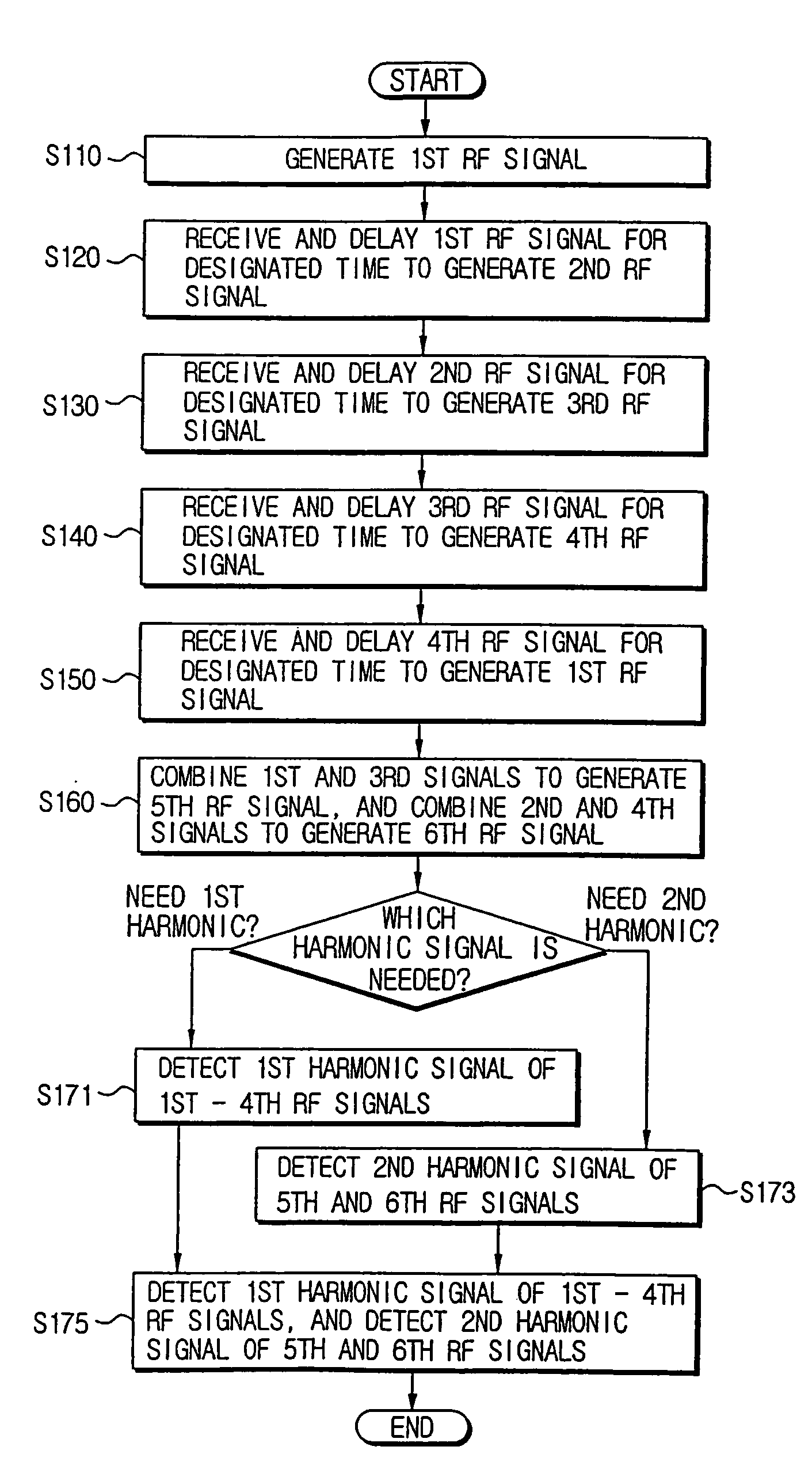
[0057]Embodiments of the present invention relate to a monolithically integrated frequency multiplier VCO circuit in CMOS technology, generating quadrature differential phase output signals at a first harmonic, and differential phase output signals at a second harmonic. All the signals are generated at the same time, and can be detected by different output nodes. Most of the signals are decoupled from each other. Preferably, the VCO circuit may be implemented in 0.18 μm CMOS technology, though not limited thereto. Te VCO circuit includes an NMOS transistor, a PMOS transistor, an NMOS varactor diode, a spiral inductor, and an MIM capacitor. This circuit configuration is...


PUM


Abstract

A differential and quadrature harmonic voltage controlled oscillator (VCO), and a method for generating a differential and quadrature harmonic signal. The VCO may include a first oscillation unit for generating a first and a third signal, a first combining unit for combining the first and the third signal, a second oscillation unit for generating a second and a fourth signal, and a second combining unit for combining the second and the fourth signal. The phase of the second signal is determined through a phase-invert and delay using the first signal, the phase of the third signal is determined through a phase-invert and delay using the second signal, the phase of the fourth signal is determined through a phase-invert and delay using the third signal, and the phase of the first signal is determined through a phase-invert and delay using the fourth signal.

Description

CROSS-REFERENCE TO RELATED APPLICATIONS[0001]This application claims benefit under 35 U.S.C. § 119 from Korean Patent Application No. 2004-9850 filed on Feb. 14, 2004, the entire content of which is incorporated herein by reference.BACKGROUND OF THE INVENTION[0002]1. Field of the Invention[0003]The present invention relates in general to a voltage controlled oscillator (hereinafter, referred to as a ‘VCO’), and more particularly, to a VCO generating multi-phase, multi-harmonic output signals.[0004]2. Description of the Related Art[0005]A voltage controlled oscillator (VCO) is an oscillator whose frequency is adjusted by controlling an applied voltage and changed capacitance of a variable capacitor.[0006]VCOs are essential components in the architecture of all telecommunication systems. The VCO in modern data communication systems is employed as part of a phase locked loop (hereinafter, referred to as a ‘PLL’) that generates local oscillator (hereinafter, referred to as an ‘LO’) freq...

Claims


Application Information

Patent Timeline
Patent Type & Authority Patents(United States)
IPC IPC(8): H04B7/00H03L7/07G11C11/00
CPCH03L7/0995H03B27/00E05B47/026E05B49/00
Inventor HOLGER, KUHNERT
Owner SAMSUNG ELECTRONICS CO LTD
Why Eureka
Try Eureka