Variable capacitor having a rigidity-increasing feature

a capacitor and variable technology, applied in the field of variable capacitors, can solve the problems of deformation of the movable capacitor electrode, deformation non-uniform distance between the two capacitor electrodes, so as to reduce the snap-together of the capacitor electrode, increase the tuning range of the capacitor, and reduce the snap-together effect of the capacitor electrod

Inactive Publication Date: 2006-02-28
AGILENT TECH INC
View PDF5 Cites 11 Cited by
  • Summary
  • Abstract
  • Description
  • Claims
  • Application Information

AI Technical Summary

Benefits of technology

[0006]The present invention pertains to a variable capacitor. An embodiment in accordance with the invention provides a variable capacitor comprising a movable capacitor electrode including a major surface and a fixed capacitor electrode including a major surface. The major surface of the fixed capacitor electrode is opposite the major surface of the movable capacitor electrode and is separated therefrom by a gap. The major surface of the movable capacitor electrode includes a rigidity-increasing feature. The rigidity-increasing feature further provides a capacitance-increasing topography and reduces snap-together of the capacitor electrodes. Reducing snap-together increases the tuning range of the capacitor.
[0007]Another embodiment provides a method of reducing snap-together between a movable capacitor electrode and a fixed capacitor electrode in a variable capacitor. The method comprises forming a fixed capacitor electrode having a major surface. The method further comprises forming a movable capacitor electrode having a major surface with a rigidity-increasing feature that reduces snap-together of the capacitor electrodes. The major surface of the movable capacitor electrode is formed opposite the major surface of the fixed capacitor electrode.
[0008]Embodiments in accordance with the invention provide a variable capacitor that has a rigid movable capacitor electrode that reduces the likelihood that movable capacitor electrode will bend, thus the distance between the capacitor electrodes is kept more uniform and predictable than conventional solutions. Embodiments in accordance with the invention provide a variable capacitor whose electrodes do not snap together as readily as conventional flat parallel-plate variable capacitors. Embodiments in accordance with the invention provide a variable capacitor with a major surface of a movable capacitor electrode and a major surface of a fixed capacitor electrode that each have a capacitance-increasing topography. In this fashion, a greater capacitance is achieved than conventional flat parallel-plate variable capacitors occupying the same chip area. Embodiments in accordance with the invention provide a variable capacitor having a greater capacitance range than conventional flat parallel-plate variable capacitors.

Problems solved by technology

A problem with conventional parallel-plate micromachined variable capacitors is keeping the distance between the movable and fixed capacitor electrodes uniform across the opposed surfaces of the capacitor electrodes.
Consequently, the distance between the two capacitor electrodes is non-uniform across the surface of the electrodes.
Moreover, because the movable capacitor electrode can bend either convexly or concavely, the capacitance of the device either decreases or increases unpredictably.
Further, bending can occur during fabrication of the capacitor, (due to variations in the internal stresses of the deposited materials,) resulting in a deformed movable capacitor electrode.
The amount by which the capacitance of conventional parallel-plate micromachined variable capacitors can be varied is limited.
Moreover, such capacitors are susceptible to a snap-together effect in which the movable capacitor electrode snaps into contact with the fixed capacitor electrode if the two capacitor electrodes get too close together.
When the capacitor electrodes get too close together, the electrostatic force overwhelms the force from the springs, and the capacitor electrodes snap together.
However, because the movable electrode could be deformed and also has a tendency to bend, snap-together can occur even if the movable capacitor electrode has moved less that ⅓ of the initial gap.
The snap-together effect prevents achieving a larger change in capacitance that would otherwise be achievable if the capacitor electrodes could be brought closer together.
Moreover, if the capacitor electrodes do snap together, a high current can flow that could damage other components in the integrated circuit.
Thus, one problem with conventional parallel-plate variable capacitors is that the movable capacitor electrode is subject to bending, so that the capacitance changes unpredictably.
Another problem with conventional parallel-plate variable capacitors is that the range of capacitance is too limited due to the snap-together effect.
Still another problem with conventional parallel-plate variable capacitors is that components can be damaged if the capacitor electrodes short together.

Method used


Image

  • Variable capacitor having a rigidity-increasing feature
  • Variable capacitor having a rigidity-increasing feature
  • Variable capacitor having a rigidity-increasing feature

Examples


Embodiment Construction

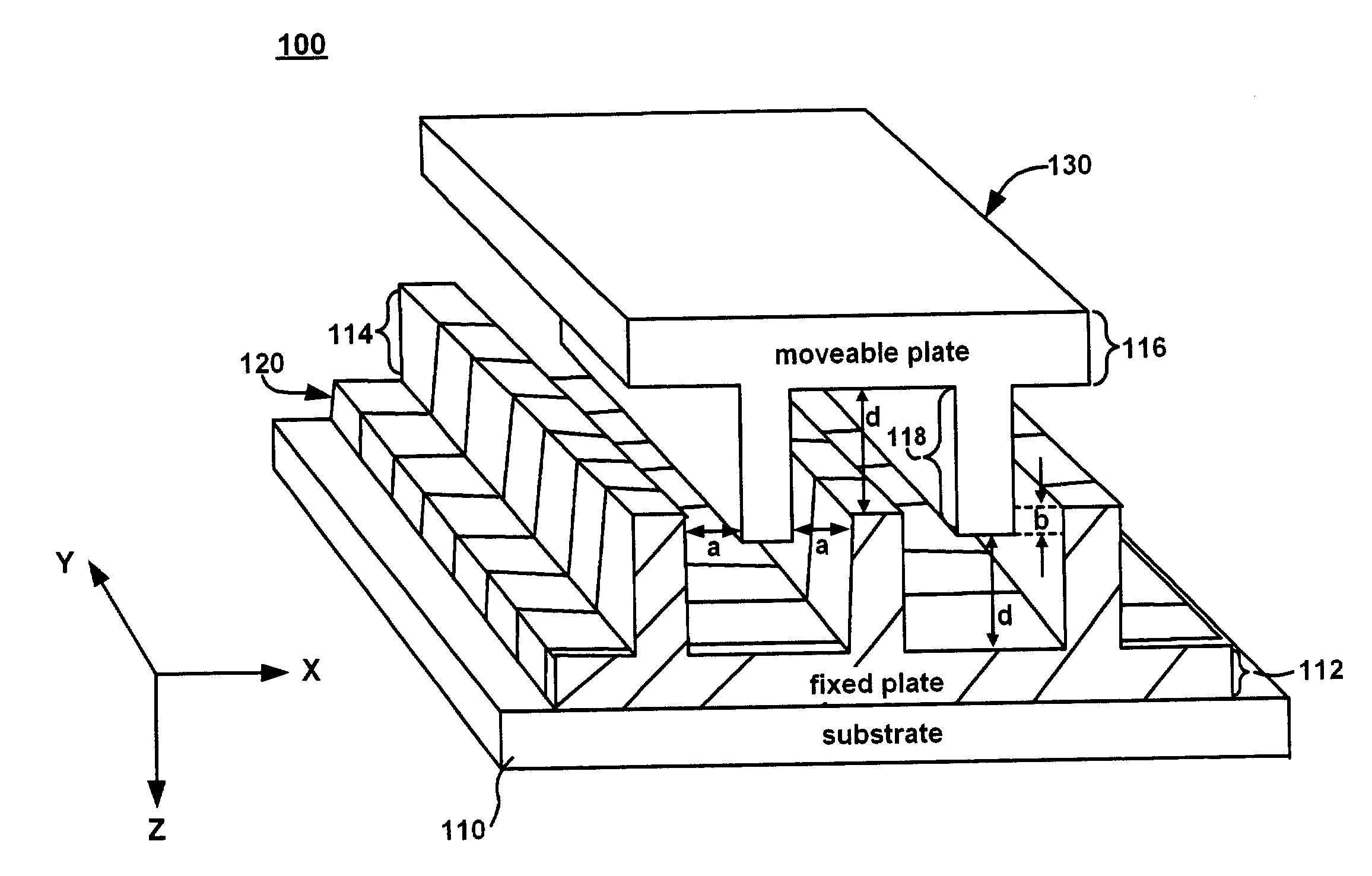
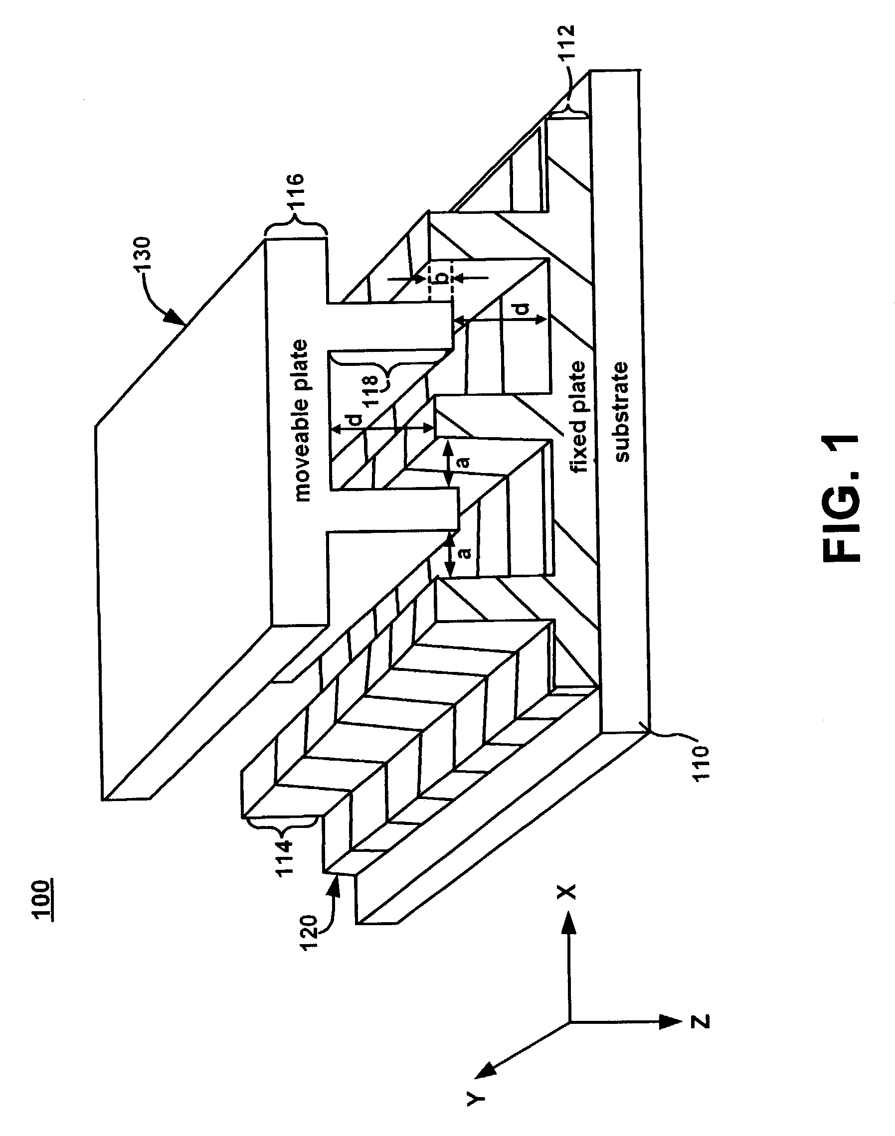
[0015]FIG. 1 illustrates a portion of an exemplary variable capacitor 100 in accordance with a first embodiment of the present invention. The movable capacitor electrode 130 of the exemplary variable capacitor 100 has rigidity-increasing features that increase the resistance of the movable capacitor electrode 130 to bending. The more rigid movable capacitor electrode 130 will not bend as easily as a conventional flat-plate capacitor when subjected to stresses such as those encountered during fabrication. The more rigid movable capacitor electrode 130 will not bend as easily as a conventional flat-plate capacitor during use.

[0016]The rigidity-increasing features of the movable capacitor electrode 130 also provide a capacitance-increasing topography. Furthermore, the fixed capacitor electrode 120 includes capacitance-increasing features. Thus, the major surfaces of the capacitor electrodes 120, 130 of the variable capacitor 100 have a capacitance-increasing topography. For the purpose...


PUM


Abstract

A variable capacitor. The variable capacitor has a movable capacitor electrode including a major surface and a fixed capacitor electrode including a major surface. The major surface of the fixed capacitor electrode is opposite the major surface of the movable capacitor electrode and is separated therefrom by a gap. The major surface of the movable capacitor electrode includes a rigidity-increasing feature. The rigidity-increasing feature further provides a capacitance-increasing topography and reduces snap-together of the capacitor electrodes.

Description

TECHNICAL FIELD[0001]Embodiments in accordance with the present invention relate to the field of variable capacitors. Specifically, embodiments in accordance with the present invention relate to a variable capacitor with a movable capacitor electrode having a rigidity-increasing feature.BACKGROUND ART[0002]It is desirable for many applications to have a tunable integrated circuit capacitor. For example, communication devices have a need for voltage controlled oscillators (VCO). Micro-electro-mechanical systems (MEMS) provide a way to construct a variable capacitor within an integrated circuit. Conventionally, a parallel-plate micromachined variable capacitor is fabricated by forming a fixed capacitor electrode on a substrate, and forming a movable capacitor electrode that is held in place parallel to the fixed capacitor electrode by a system of springs. By applying a control voltage between the fixed and movable capacitor electrodes, the movable capacitor electrode is pulled towards...

Claims


Application Information

Patent Timeline
Patent Type & Authority Patents(United States)
IPC IPC(8): H01G7/00H01G7/06H01G5/14H01G5/16
CPCH01G5/16H01G5/14
Inventor WILLIAMS, KIRT R.MATTA, FARID
Owner AGILENT TECH INC
Why Eureka
Try Eureka