
Total joint arthroplasty system

a total joint and arthroplasty technology, applied in the field of value added medical devices, can solve the problems of lack of micron-level geometric accuracy, many surgeons are unable to exert a precise, predefined force in a selected direction, and surgeons have limitations, so as to minimize additional expenditures for capital equipment purchases, accurate cutting, and increase surgical time

Inactive Publication Date: 2013-07-25
HOWMEDICA OSTEONICS CORP
View PDF6 Cites 21 Cited by
  • Summary
  • Abstract
  • Description
  • Claims
  • Application Information

AI Technical Summary

Benefits of technology

[0015]One feature of the invention is use of an image-based surgical system in total joint arthroplasty, such as total hip arthroplasty (THA), total knee arthroplasty (TKA), total elbow arthroplasty (TEA), spinal surgery, etc. The system software receives or provides geometrical information on the damaged bone, captured in CT or another suitable imaging format, and converts his information into a three-dimensional (3D) model of the bone surfaces during the computer-aided pre-operative planning. The converted 3-D model includes the information on corresponding bone dimensions along with the uncertainties associated with CT scanning and conversion errors. The system displays all the pertinent information on the damaged bones on the screen. The system provides a surgeon with improved visualization of the relationship between the damaged bone and the cutting jig or implant device, including but not limited to accurate alignment of the device, by accurately superimposing representations of a cutting jig and / or an implant device being used in the surgical field over the images of the bone.
[0021]These features and advantages of the present invention are embodied in an improved system for assisting a surgeon in using a surgical tool to provide accurate cutting, implant positioning and alignment with respect to one or more body parts. The system uses a computer-aided calibration process involving a surface matching of the cutting jig and / or implant device to the bone surface(s). Because the cutting jig and / or implant device is fabricated using CT scan image data, there is no need for use of a registration process, expensive tracking systems or robotic systems in an operating room, or for use of two or more surgical procedures. The invention is designed to work in conjunction with any manual standard TJA instrumentation, and thus minimizes additional expenditures for capital equipment purchases. Furthermore, there is no increase in surgical time, and the cutting jig and / or implant device can provide a reduction in surgical time.

Problems solved by technology

However, surgeons have limitations, including a lack of micron-level geometric accuracy.
Many surgeons are unable to exert a precise, predefined force in a selected direction.
Furthermore, a surgeon may have small hand tremors that limit his / her ability to operate on very small and delicate structures.
Unfortunately, many of these limitations affect the outcome of certain surgical procedures, especially in cases where micron-level geometric accuracy is required.
The second surgical operation is constrained by a tourniquet time limitation, which places a practical limit on a maximum cumulative time an open wound can be exposed (usually 90-120 min for TKA) without severe danger of infection.
This is another disadvantage of robot-assisted surgery, which requires use of a registration process and of a bone location fixation process, both time consuming.
As compared to robot-assisted surgery, a conventional manual TKA procedure is usually completed in no more than 30 minutes, despite a relatively high probability of misalignment.
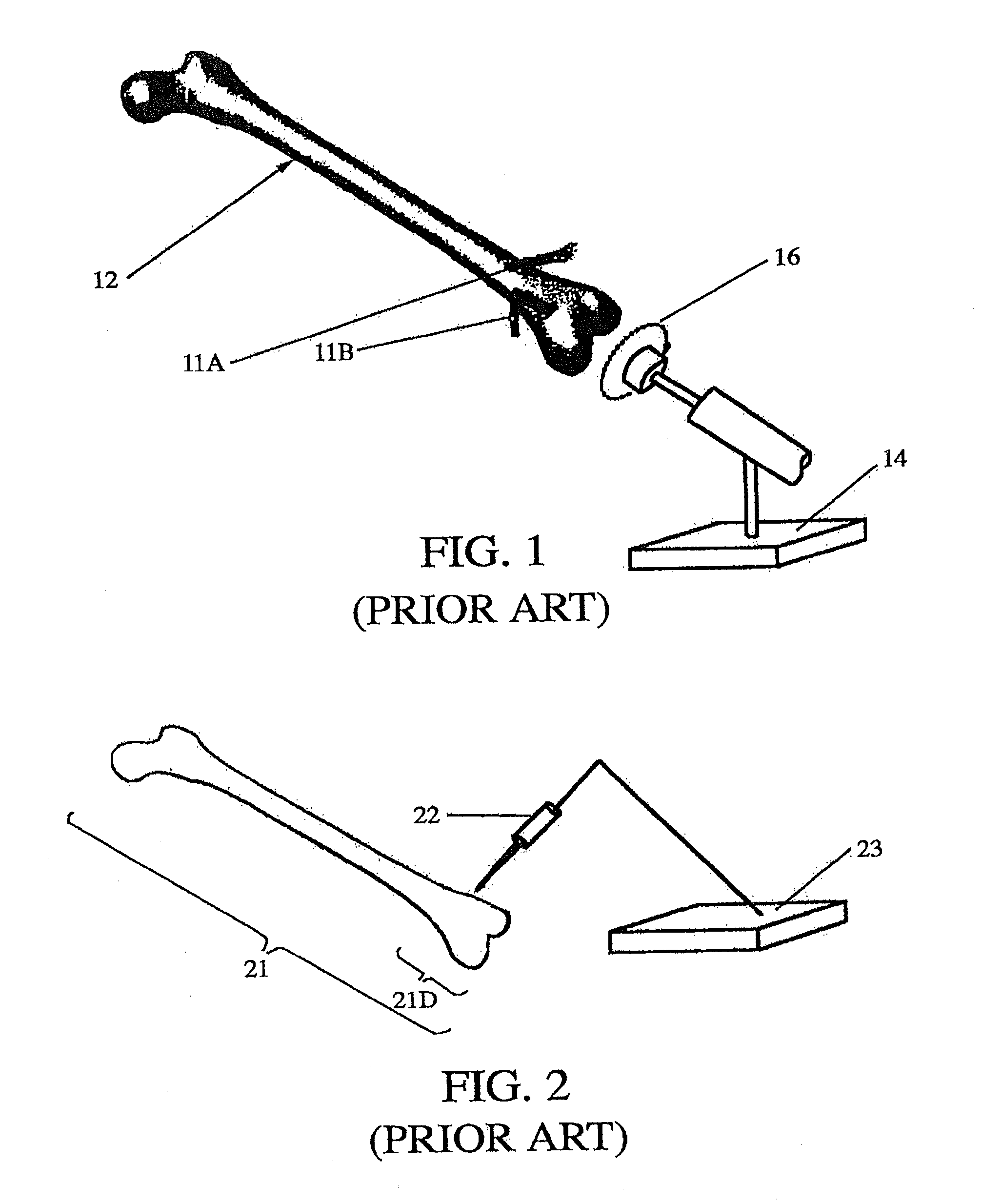
A disadvantage of the devices illustrated in FIGS. 1 and 2 is that they require additional surgical time, require a direct line of sight to perform the procedure, require special training of surgeon and staff, require maintenance and frequent calibration of the robotic mechanism(s), and can be very expensive, depending on the required level of accuracy.
Such devices do not require a direct line of sight, but the devices may be less accurate, cannot be used with metallic tools, and have difficulties tracking multiple tools simultaneously.
The systems described in the preceding discussion often suffer from a lack of readiness for the operating room and do not always address practical considerations.
Further, most of the systems do not address the issues of sterility and safety, and unwanted motion of the body part(s) to be operated upon.
Many systems rely on a non-sterile assistant to enter data, using a keyboard, mouse or pen, but this is inefficient and risks miscommunication.
A sterilized or draped input device, introduced into the surgical operating theater, may be difficult to use, may be distracting for the surgeon, requires the splitting of the surgeon's attention between the display screen in one location and the surgical tool in another, and requires removal of the tool from the surgical site for use elsewhere as an input device.

Method used


Image

  • Total joint arthroplasty system
  • Total joint arthroplasty system
  • Total joint arthroplasty system

Examples


Embodiment Construction

1) System Architecture

[0036]In a preferred embodiment, the invention provides accurate positioning and alignment of an orthopedic implant without a significant increase in surgical time or capital equipment cost. Also, during the actual surgery, the system does not require use of registration, image matching or location tracking, which distinguishes the invention from other image-based systems.

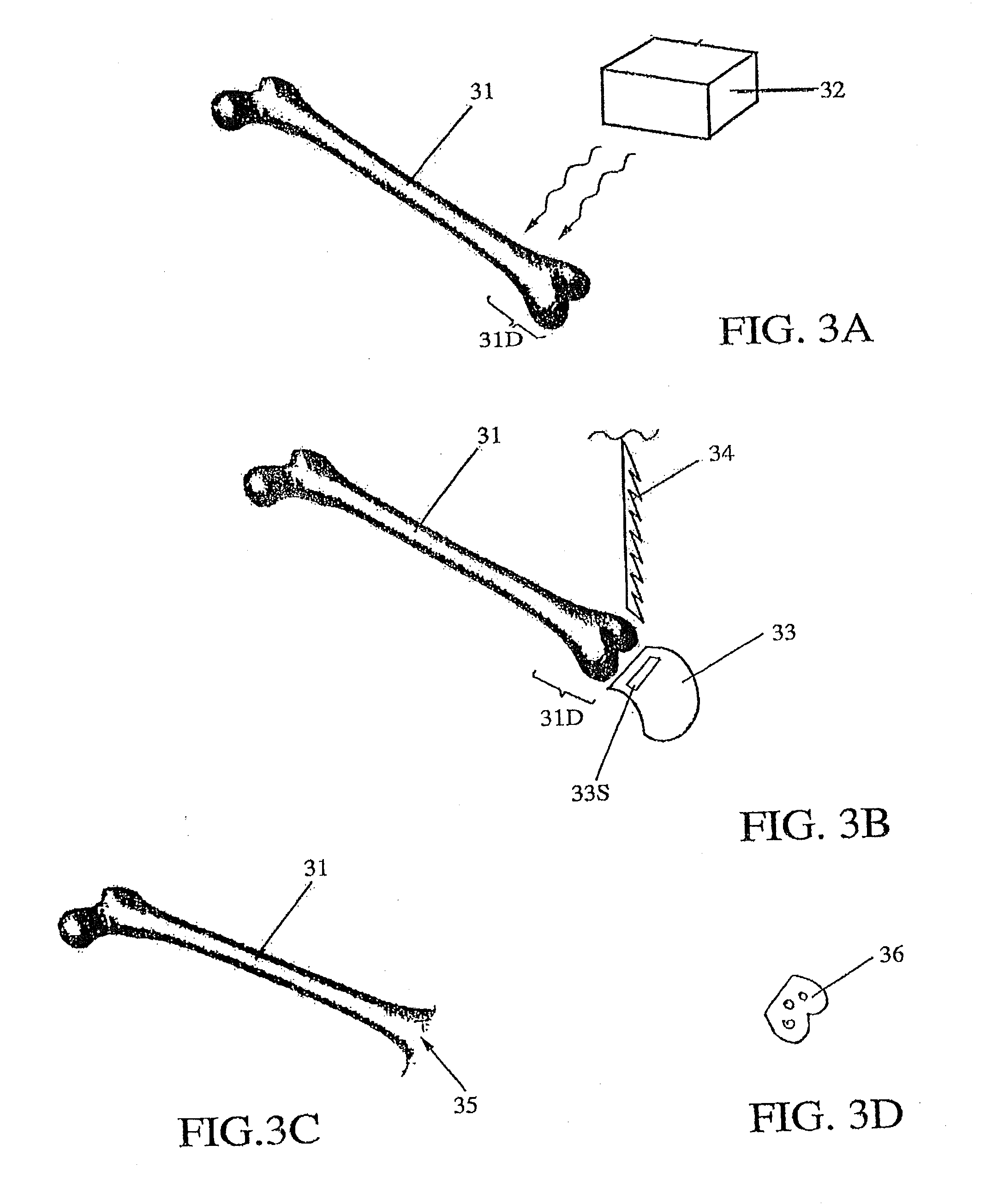
[0037]FIGS. 3A, 3B, 3C and 3D illustrate some features of the invention, A damaged region 31D of a target bone 31 undergoes CT scan in FIG. 3A. Pre-operative planning is performed, using a computer and a CT image scanner 32, to construct a model of bone surfaces adjacent to the damaged region 31D, with an associated inaccuracy of no more than 90 μm. Based on the accumulated planning data, a production file is created to receive the CT image data and to fabricate a jig or cutting block and, optionally, an implant device. The production file and the planning information are sent to the productio...


PUM


Abstract

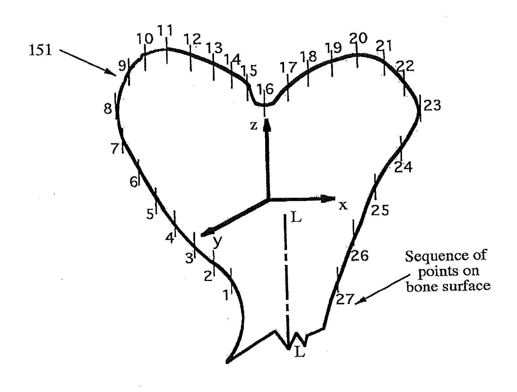
A method and system for performing a total joint arthroplasty procedure on a patient's damaged bone region. A CT image or other suitable image is formed of the damaged bone surfaces, and location coordinate values (xn,yn,zn) are determined for a selected sequence of bone surface locations using the CT image data. A mathematical model z=f(x,y) of a surface that accurately matches the bone surface coordinates at the selected bone spice locations, or matches surface normal vector components at selected bone surface locations, is determined. The model provides a production file from which a cutting jig and an implant device (optional), each patient-specific and having controllable alignment, are fabricated for the damaged bone by automated processing. At this point, the patient is cut open (once), the cutting jig and a cutting instrument are used to remove a selected portion of the bone and to provide an exposed planar surface, the implant device is optionally secured to and aligned with the remainder of the bone, and the patient's incision is promptly repaired.

Description

FIELD OF THE INVENTION[0001]This invention relates to fabricating a value added medical device for patient-specific, total joint arthroplasty (TJA) procedures. More specifically, the invention relates to a system for producing a value added medical device or instrument (collectively referred to as a “medical device” herein), based on computer tomography (CT) or other imaging of a region of the body adjacent to a selected joint.BACKGROUND OF THE INVENTION[0002]Surgeons are generally dexterous and highly trained to achieve a standardized level of surgical skill. However, surgeons have limitations, including a lack of micron-level geometric accuracy. For example, a surgeon cannot place an instrument at an exact, numerically defined location (within, say, 100 μm) relative to a patient's body part and then move the instrument through a defined trajectory. Many surgeons are unable to exert a precise, predefined force in a selected direction. Furthermore, a surgeon may have small hand trem...

Claims


Application Information

Patent Timeline
Patent Type & Authority Applications(United States)
IPC IPC(8): A61B17/17G06F19/00A61F2/30G16Z99/00
CPCA61B17/154G06F17/5009A61B2019/505A61B2019/524A61B17/1739A61B17/1703A61B19/50A61B17/17A61F2/30G06F19/3437A61B2019/508A61B17/155A61B2019/502A61B2017/00526A61B17/1764A61B2034/102A61B2034/105A61B2034/108A61B2090/3762A61B2034/104B29C64/386G16H50/50A61B34/10B33Y80/00B33Y50/00G16Z99/00A61B17/1668A61B17/1675A61B6/032A61B17/171B29C64/393A61B2017/568G06F30/20B33Y50/02G05B19/4099G05B2219/35134A61B17/157
Inventor PARK, ILWHANPEARSON, LACERIALSAMUEL, STEPHEN M.SCHIPPER, JOHN
Owner HOWMEDICA OSTEONICS CORP
Learn More