

Compact hyperspectral imager
a hyperspectral imager and compact technology, applied in the field of hyperspectral imagers, can solve the problems of limited compactness of catadioptric spectrometers, and achieve the effects of reducing mechanical alignment tolerances, simplifying mounting configuration, and limited compactness
- Summary
- Abstract
- Description
- Claims
- Application Information
AI Technical Summary
Benefits of technology
Problems solved by technology
Method used
Image

Examples
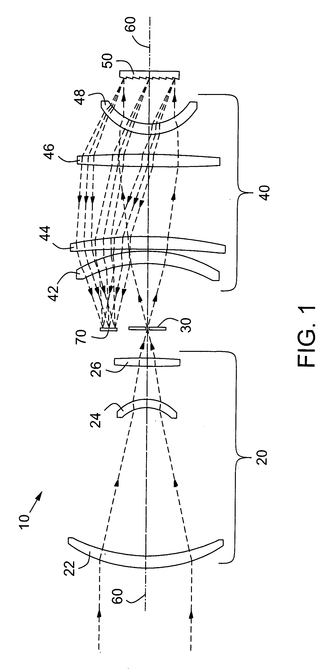
embodiment 10
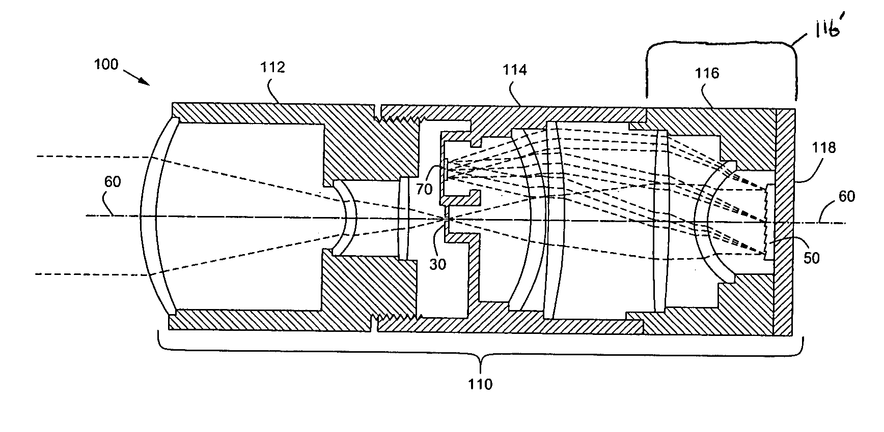
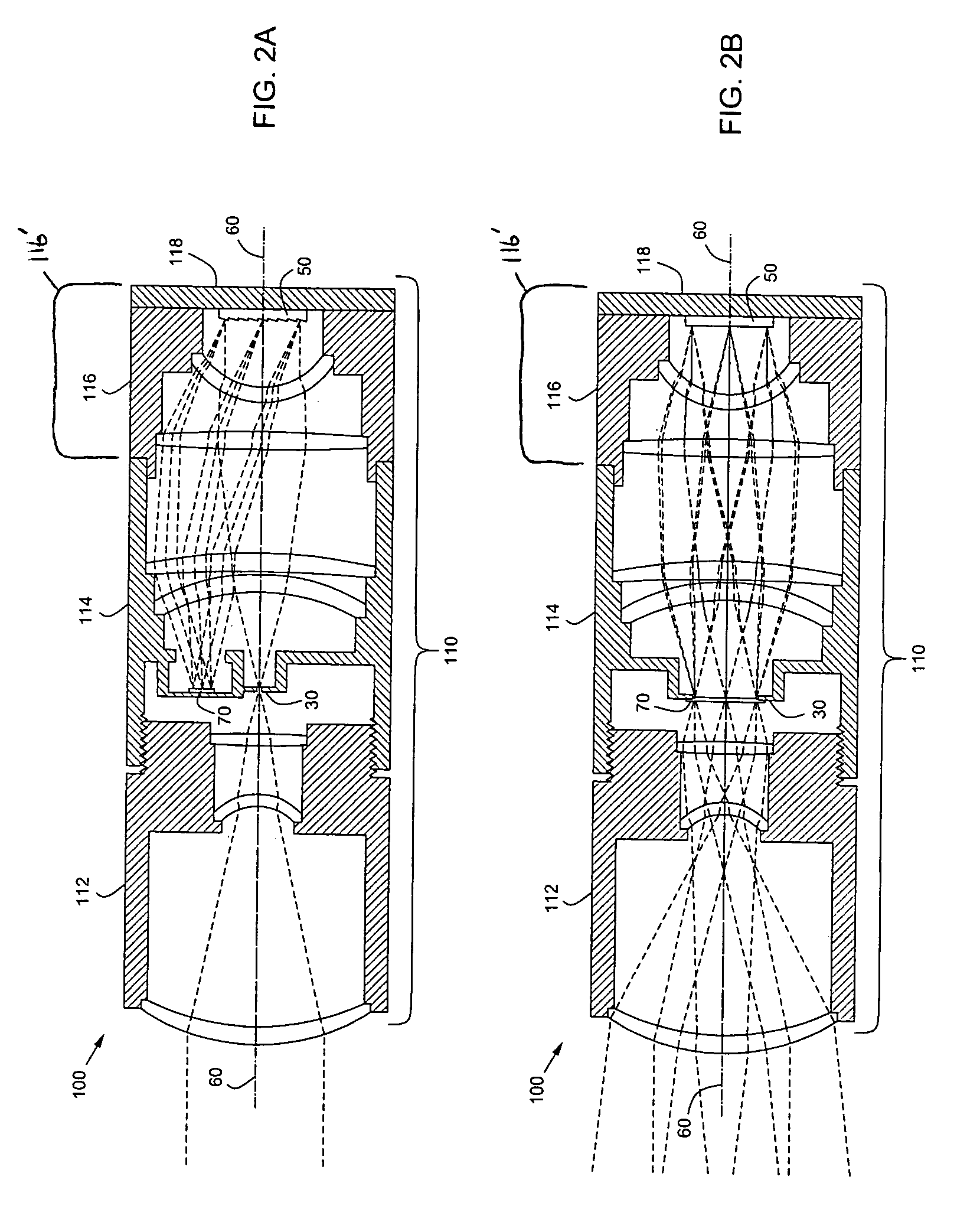
[0023]Some of the advantages of this inline configuration can be seen in FIG. 2A, which illustrates a mounted version of system 10 in the present invention, taken along the optical axis 60 in the plane parallel to the direction of dispersion. This mounted system 100 consists of the previous embodiment 10 illustrated in FIG. 1 mounted in a typical housing 110, which is composed of housing subassemblies 112, 114, 116, and 118, and illustrates the simplified mounting configuration and overall compactness of this system.
[0024]Referring again to FIG. 2A, at least one optical component from the optical lens assembly 20 is positioned within the first housing subassembly 112. The first housing subassembly 112 defines a first interior longitudinal axis. An optical axis of the optical components positioned within the first housing subassembly 112 is substantially coincident with the first interior longitudinal axis. In the embodiment shown in FIG. 2A, all components 22, 24 and 26 of the optic...
embodiment 200
[0029]Some of the advantages of the above embodiment can be seen in FIG. 4A, which illustrates a mounted version of system 200 in the present invention, taken along the optical axis 60 in the plane parallel to the direction of dispersion. The mounted system 300 of FIG. 4A consists of a modification of the previous embodiment 200 illustrated in FIGS. 2A and 2B mounted in a typical housing 310, which is composed of housing subassemblies 112, 314, 116, and 118, and illustrates the increased accessibility to the detecting element 70, which is now located at the outside of the mechanical housing 314, without compromising the compact nature of the system. Housing subassemblies 112, 116, and 118 are unchanged from embodiment shown in FIGS. 2A and 2B. The redirecting optical element (the fold prism) 280, the detecting element 70, one or more one slit elements 30 and at least one optical component from the optical subassembly 40 are positioned within the second housing subassembly 314.
[0030]...
embodiment 400
[0032]Some of the advantages of the above embodiment can be seen in FIG. 6A, which illustrates a mounted version of system 400 in the present invention, taken along the optical axis 60 in the plane parallel to the direction of dispersion. This mounted system 500 consists of the previous embodiment 400 illustrated in FIG. 4 mounted in a typical housing 510, which is composed of housing subassemblies 512, 514, 516, and 518. The fold prism assembly 480 is positioned such that both detecting elements do not obstruct the path of the light through the system without compromising the overall compactness of the system.
[0033]The mounted system 500 of FIG. 6A consists of a modification of the previous embodiment 200 illustrated in FIGS. 2A and 2B mounted in a typical housing 510, which is composed of housing subassemblies 512, 514, 516, and 518. Housing subassemblies 116 and 118 are unchanged from embodiment shown in FIGS. 2A and 2B. Housing subassembly 512 is similar to housing subassembly 1...
PUM
 Abstract
Description
Claims
Application Information