Optical integrated circuit and optical integrated circuit module
a technology of optical integrated circuit and integrated circuit module, which is applied in the direction of optical waveguide light guide, optical light guide, instrument, etc., can solve the problems of troublesome optical alignment work, increased possibility of alignment error, and difficulty in obtaining excellent coupling efficiency, so as to achieve excellent coupling efficiency. excellent
- Summary
- Abstract
- Description
- Claims
- Application Information
AI Technical Summary
Benefits of technology
Problems solved by technology
Method used
Image
Examples
first embodiment
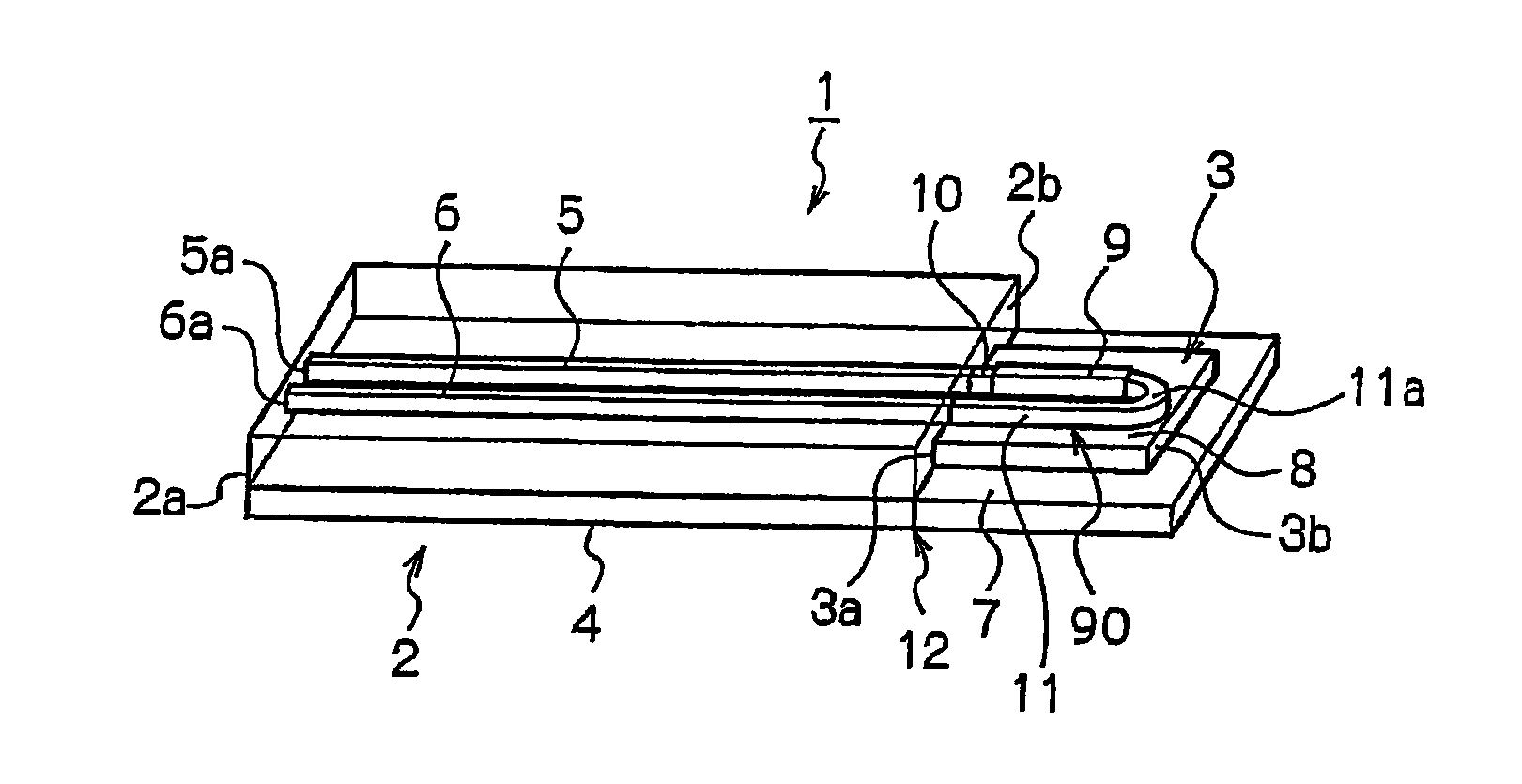
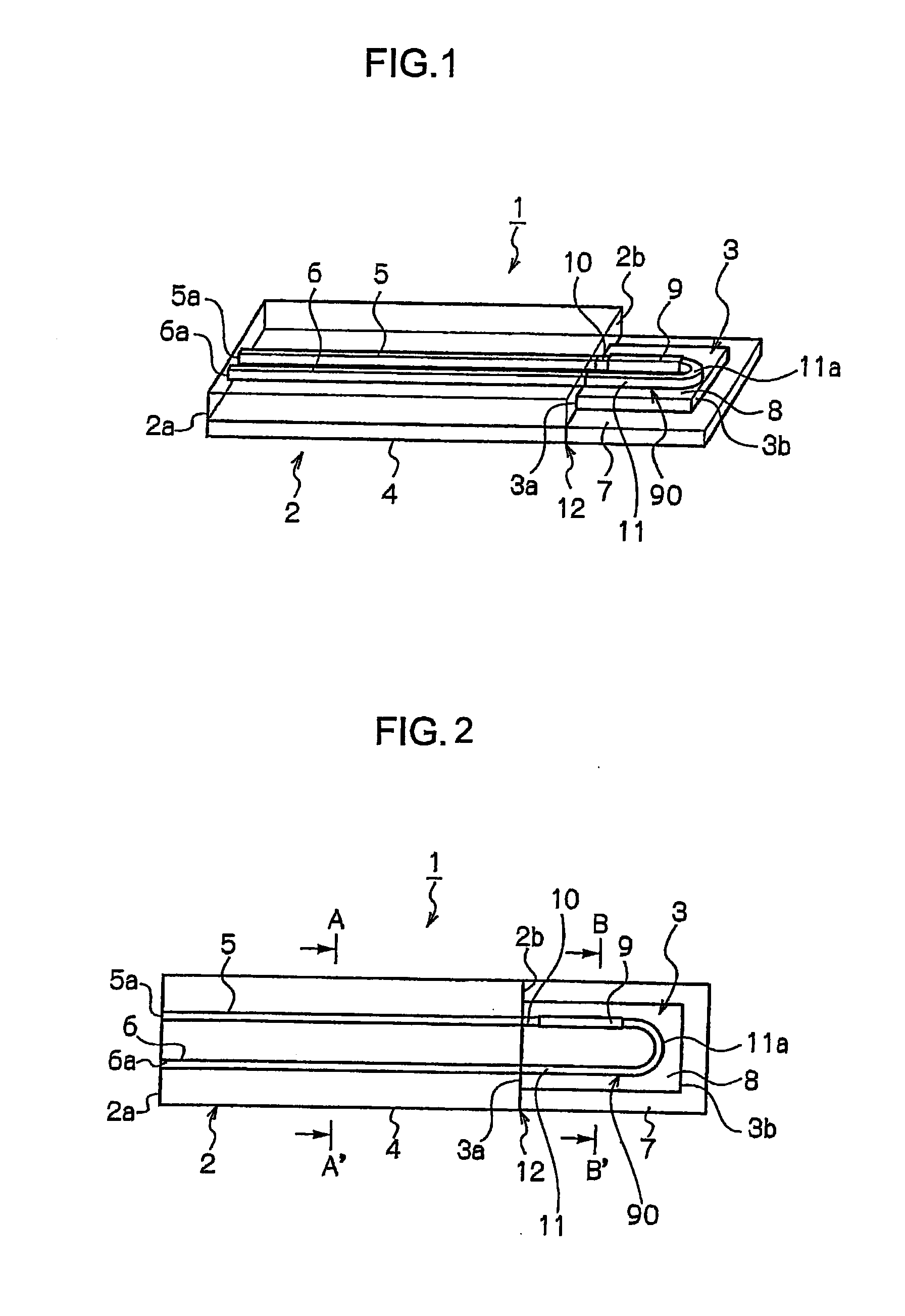
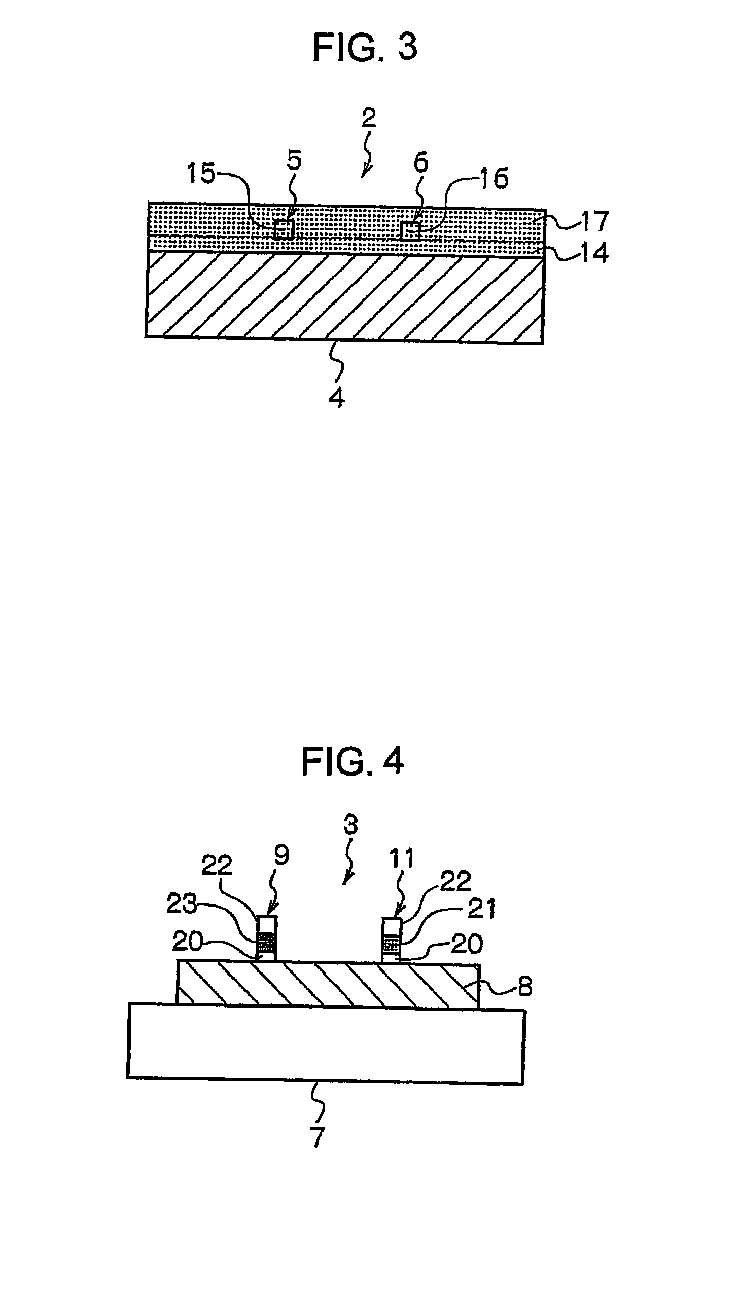
[0058]An optical integrated circuit in accordance with a first embodiment of the present invention will be described based on FIG. 1 through FIG. 4. FIG. 1 is a conceptual diagram showing a basic configuration of the optical integrated circuit in accordance with the first embodiment, while FIG. 2 is a plan view showing the same optical integrated circuit. FIG. 3 is a sectional view along a line A-A′ shown in FIG. 2, and shows a cross-sectional structure of the planar lightwave circuit. Meanwhile, FIG. 4 is a sectional view along a line B-B′ shown in FIG. 2, and shows a cross-sectional structure of a semiconductor waveguide portion of a semiconductor element.
[0059]An optical integrated circuit 1 is a circuit in which a planar lightwave circuit (PLC) 2 and a semiconductor element 3 fixed on a silicon substrate 7 are integrated as shown in FIG. 1 and FIG. 2.
[0060]The planar lightwave circuit 2 is provided with a PLC platform 4 and two straight optical waveguides 5 and 6 formed on the P...
second embodiment
[0086]Next, an optical integrated circuit in accordance with a second embodiment will be described based on FIG. 5 and FIG. 6. FIG. 5 is a conceptual diagram showing a schematic configuration of an optical integrated circuit 1A in accordance with a second embodiment, while FIG. 6 is a plan view showing the optical integrated circuit 1A.
[0087]The optical integrated circuit 1A is characterized in that, in the optical integrated circuit 1 in accordance with the aforementioned first embodiment shown in FIG. 1, a plurality of semiconductor optical amplifiers (elements) are arranged in array pattern on the semiconductor substrate 8 of a semiconductor element 3A. As an example, four semiconductor optical amplifiers 91 to 94 are arranged in array pattern on the semiconductor substrate 8 as shown in FIG. 5 and FIG. 6 in the present embodiment.
[0088]Meanwhile, there are formed on the semiconductor substrate 8 the input semiconductor waveguides 101 to 104 and the output semiconductor waveguide...
third embodiment
[0098]Next, an optical integrated circuit in accordance with a third embodiment will be described based on FIG. 7. FIG. 7 is a conceptual diagram showing a schematic configuration of an optical integrated circuit 1B in accordance with the third embodiment.
[0099]The optical integrated circuit 1B is characterized by following configurations.
[0100]A semiconductor element 3B in which a plurality of waveguide-type photodiodes (elements) 301 to 306 are formed on the semiconductor substrate 8 in array pattern, and a planar lightwave circuit 2B in which a plurality of optical waveguides are formed are fixed at one contact surface 12 and are integrated. As an example, six waveguide photodiodes 301 to 306 are formed on the semiconductor substrate 8 in the present embodiment.
[0101]Six straight optical waveguides 311 to 316 respectively coupled with the light incidence side end facets (light receiving facets) of the waveguide photodiodes 301 to 306 are formed on the PLC platform 4 of the planar...
PUM
 Abstract
Description
Claims
Application Information
 - R&D
- Intellectual Property
- Life Sciences
- Materials
- Tech Scout
- Unparalleled Data Quality
- Higher Quality Content
- 60% Fewer Hallucinations
Browse by: Latest US Patents, China's latest patents, Technical Efficacy Thesaurus, Application Domain, Technology Topic, Popular Technical Reports.
© 2025 PatSnap. All rights reserved.Legal|Privacy policy|Modern Slavery Act Transparency Statement|Sitemap|About US| Contact US: help@patsnap.com


