Microelectromechanical safing and arming apparatus

a technology of microelectromechanical and arming apparatus, which is applied in the direction of electrical equipment, contact, weapons, etc., can solve the problems of large volume of finished devices, and high cost of individual parts machining,

Inactive Publication Date: 2008-06-10
NAT TECH & ENG SOLUTIONS OF SANDIA LLC
View PDF21 Cites 13 Cited by
  • Summary
  • Abstract
  • Description
  • Claims
  • Application Information

AI Technical Summary

Benefits of technology

[0011]The first latch preferably comprises a cantilevered beam having a thickness less than the thickness of the shuttle and can further include a clasp located at a free end of the cantilevered beam for engaging with one or more tabs located on the shuttle to lock the shuttle in the first position until the shuttle is disengaged upon occurrence of the first acceleration component. The second latch can comprise one or more cantilevered beams, with each cantilevered beam having a catch formed at a free end thereof for engaging a tang projecting from the shuttle to hold the shuttle in the second position. A stop can be provided in the apparatus to prevent movement of the shuttle beyond the second position.
[0013]In other embodiments of the present invention, the shuttle can further comprise a window formed therethrough, with the window in the shuttle being misaligned with respect to an opening formed through a subbase attached to an underside of the substrate when the shuttle is in the first position, and aligned with the opening through the subbase when the shuttle is in the second position. In these embodiments of the present invention, the shuttle can provide for the transmission of light through the shuttle and subbase when the shuttle is in the second position and can block the transmission of light through the shuttle and subbase when the shuttle is in the first position. The transmission of light can be used to provide optical functionality for the two-stage acceleration sensing apparatus, or to form an optically-enabled safing and arming device.
[0017]The first latch can comprise a cantilevered beam with a clasp located at a free end thereof for engaging one or more tabs located on the shuttle. The second latch can comprise one or more catches for engaging a tang projecting from the shuttle to lock the shuttle in the second position. A stop can also be provided in the apparatus prevent an in-plane movement of the shuttle beyond the second position.

Problems solved by technology

The machining of many individual parts which must be made with close tolerances and then assembled by hand is relatively expensive and also results in a completed device which is relatively bulky.

Method used


Image

  • Microelectromechanical safing and arming apparatus
  • Microelectromechanical safing and arming apparatus
  • Microelectromechanical safing and arming apparatus

Examples


Embodiment Construction

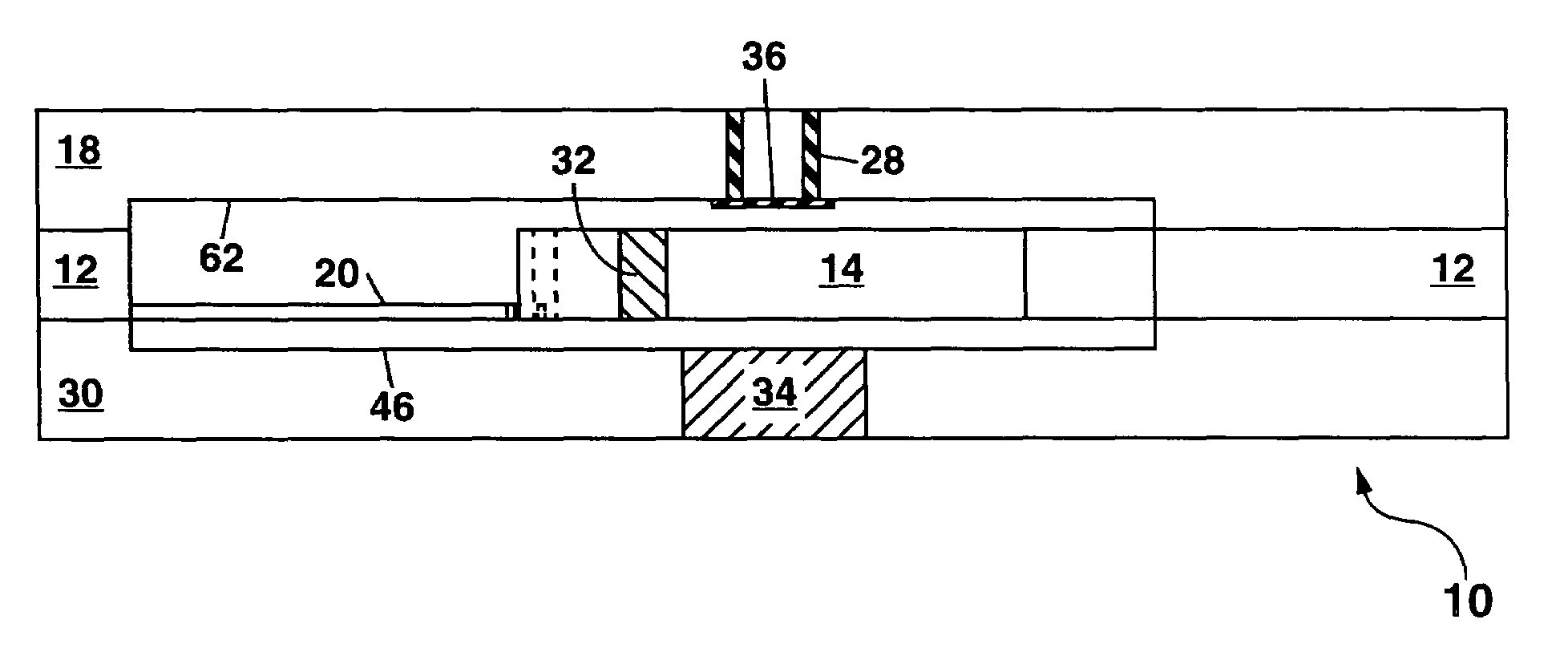
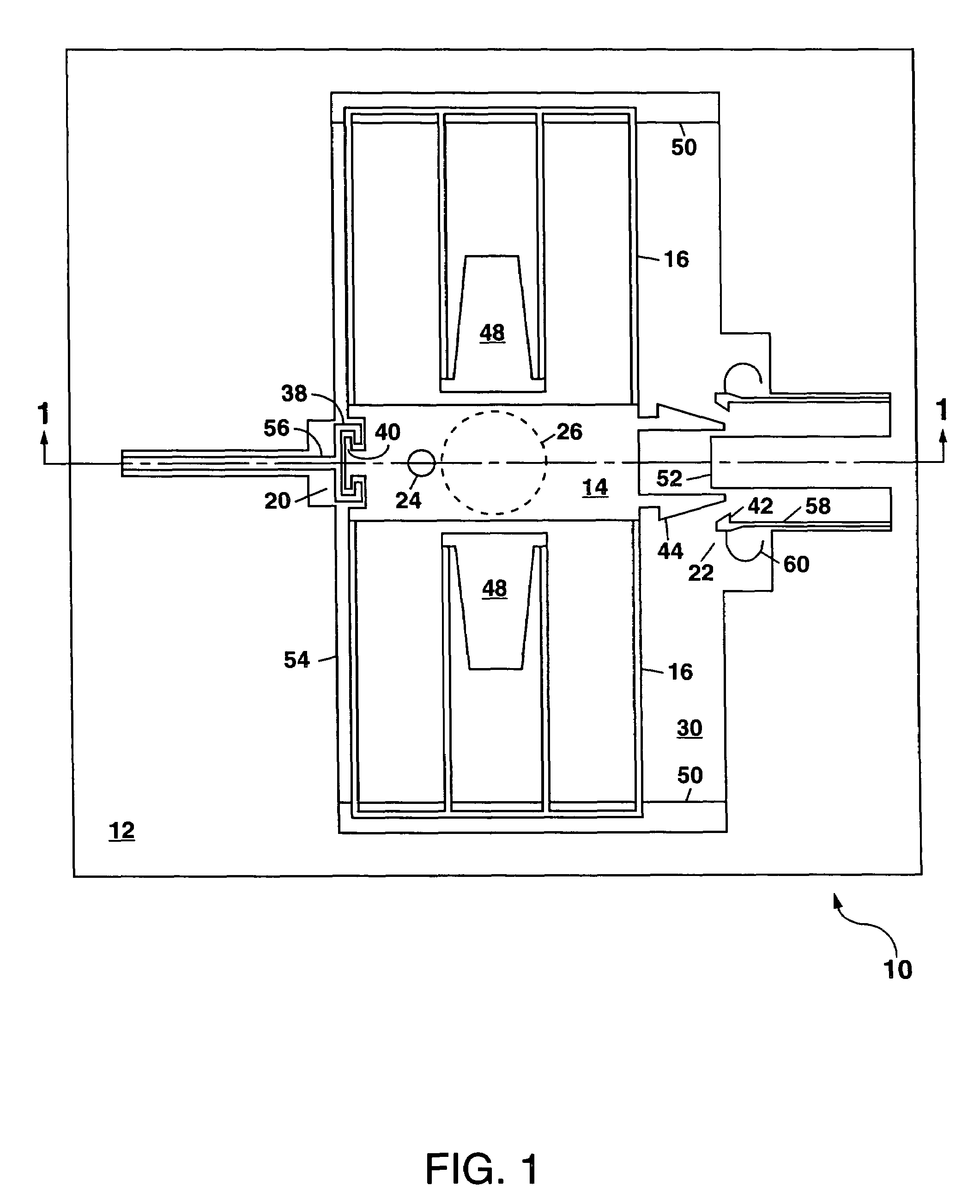
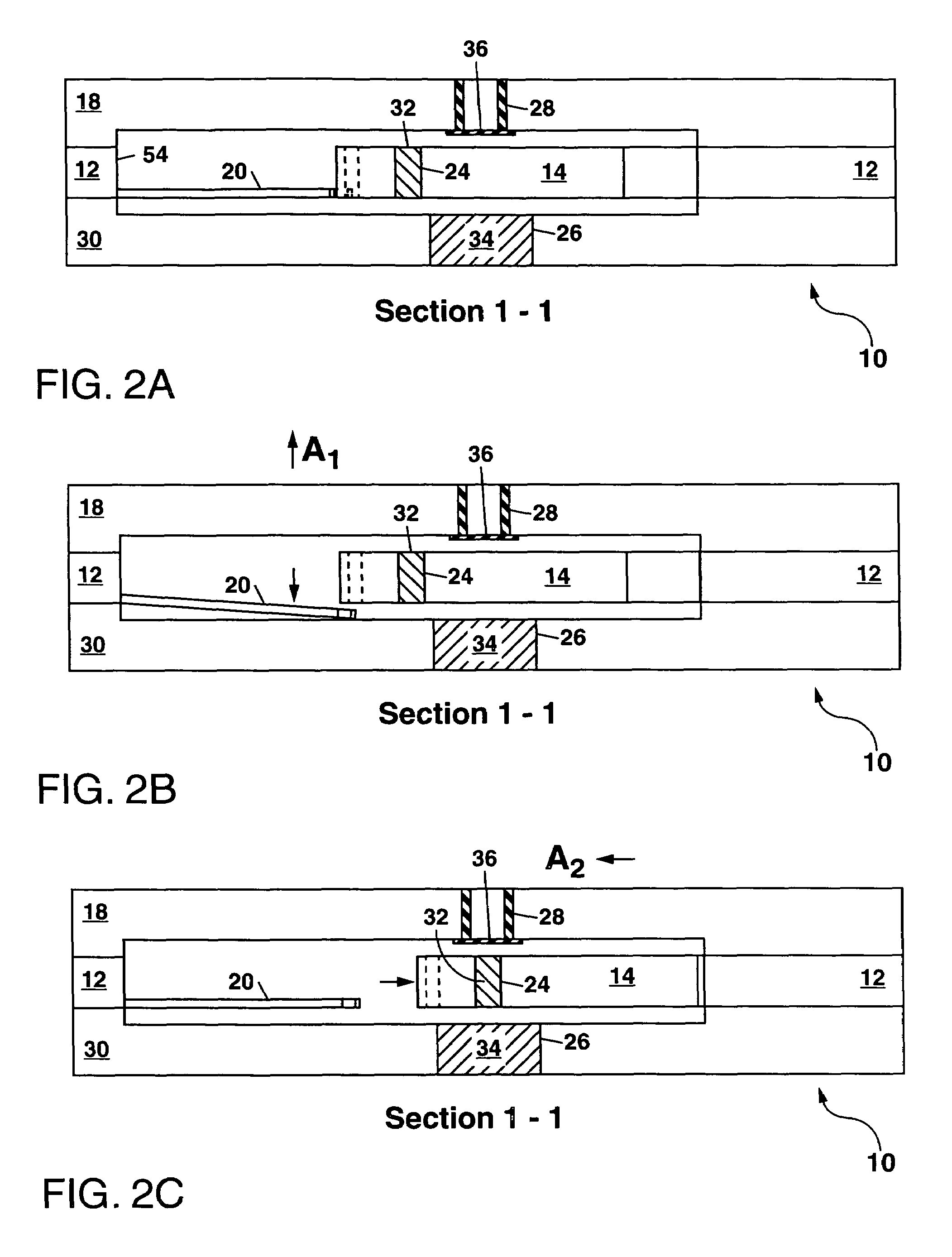
[0034]Referring to FIG. 1, there is shown a schematic plan view of a first example of the two-stage acceleration sensing apparatus 10 of the present invention which can be used as a safing and arming device in a fuze assembly for a projected munition. In FIG. 1, the apparatus 10 comprises a substrate 12, a shuttle 14 which can be formed, at least in part, from the substrate 12 and which is suspended for movement in the plane of the substrate 12 by a plurality of folded springs 16. A lid 18 which overlies the substrate 12 has been omitted from FIG. 1 for clarity, but is schematically illustrated in the cross-sectional view of FIG. 2A taken along the section line 1-1 in FIG. 1.

[0035]In FIG. 1, a first latch 20 is provided in the apparatus 10 to lock the shuttle 14 in an “as-fabricated” position (i.e. a first position) until the first latch 20 is disengaged by bending the first latch 20 downward in response to a first acceleration component (shown as A1 in FIG. 2B) which is directed su...


PUM


Abstract

A two-stage acceleration sensing apparatus is disclosed which has applications for use in a fuze assembly for a projected munition. The apparatus, which can be formed by bulk micromachining or LIGA, can sense acceleration components along two orthogonal directions to enable movement of a shuttle from an “as-fabricated” position to a final position and locking of the shuttle in the final position. With the shuttle moved to the final position, the apparatus can perform one or more functions including completing an explosive train or an electrical switch closure, or allowing a light beam to be transmitted through the device.

Description

[0001]This is a division of application Ser. No. 10 / 641,980 filed Aug. 14, 2003 now U.S. Pat. No. 7,051,656, which is pending.GOVERNMENT RIGHTS[0002]This invention was made with Government support under Contract No. DE-AC04-94AL85000 awarded by the U.S. Department of Energy. The Government has certain rights in the invention.CROSS REFERENCE TO RELATED APPLICATIONS[0003]This application is related to application Ser. No. 10 / 641,8609 filed on Aug. 14, 2003 and entitled “Microelectromechanical Acceleration Sensing Latch”.FIELD OF THE INVENTION[0004]The present invention relates in general to microelectromechanical (MEM) devices, and in particular to an apparatus for sensing acceleration along two orthogonal axes that has applications for the safing and arming of projected munitions.BACKGROUND OF THE INVENTION[0005]Safing and arming devices are generally provided in munitions as part of a fuze assembly to ensure that the munition is not armed and detonated until certain conditions have ...

Claims


Application Information

Patent Timeline
Patent Type & Authority Patents(United States)
IPC IPC(8): F42C15/24
CPCF42C15/005F42C15/184F42C15/24F42C15/26H01H2001/0047
Inventor KOEHLER, DAVID R.HOKE, DARREN A.WEICHMAN, LOUIS S.VERNON, GEORGE E.SHUL, RANDY J.BEGGANS, MICHAEL H.
Owner NAT TECH & ENG SOLUTIONS OF SANDIA LLC
Why Eureka
Try Eureka