Motorized roller transverse drive

a transverse drive and motorized technology, applied in the field of conveyors, can solve the problems of reduced power or torque, limited speed capability of conventional o-ring roller conveyors, and additional power typically lost at each idler roller, etc., and achieve the effect of raising and lowering, raising and lowering the belts, and increasing the speed

Inactive Publication Date: 2008-06-10
DEMATIC
View PDF26 Cites 31 Cited by
  • Summary
  • Abstract
  • Description
  • Claims
  • Application Information

AI Technical Summary

Benefits of technology

[0017]Therefore, the present invention provides a roller conveyor powered or driven by a transverse drive system having a motorized roller, whereby the motorized roller independently or separately drives at least some or most of the idler rollers of the zone associated with the motorized roller. The motorized roller is positioned generally transverse to the rollers and may rotatably and independently drive multiple idler rollers via respective drive members or bands. The motorized roller thus may independently drive more than only two idler rollers. The transverse drive system of the present invention thus may limit or avoid the loss of torque or power associated with the end rollers or portions of zones of conventional O-ring driven roller conveyors. The transverse drive system thus may not have the potential stall areas of conventional roller conveyors and may be operated at a higher speed than conventional roller conveyors. Also, the right angle transfer unit may be operable via a motorized roller and may be raised and lowered via a rotational drive motor. The right angle transfer unit thus may raise and lower the belts in an efficient and quiet manner, without pneumatic or hydraulic lift cylinders and the like.

Problems solved by technology

This reduction in power or torque may occur at each O-ring interface, such that additional power is typically lost at each idler roller toward the outer ends of the zone and away from the motorized roller.
Also, because of the reduced power in certain areas of the roller conveyor, such conventional O-ring roller conveyors may have limited speed capability, and may be limited to conveying articles at approximately 150 feet per minute or thereabouts.
In such applications, the rollers may have less torque or power capability away from the motorized roller and, thus, may be prone to have articles stall at the ends of the zones of the conveyor.

Method used


Image

  • Motorized roller transverse drive
  • Motorized roller transverse drive
  • Motorized roller transverse drive

Examples


Embodiment Construction

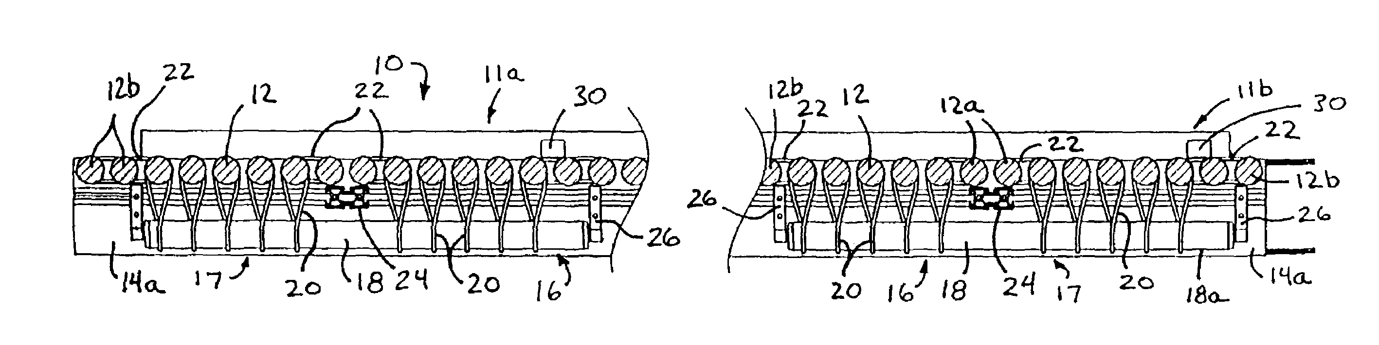
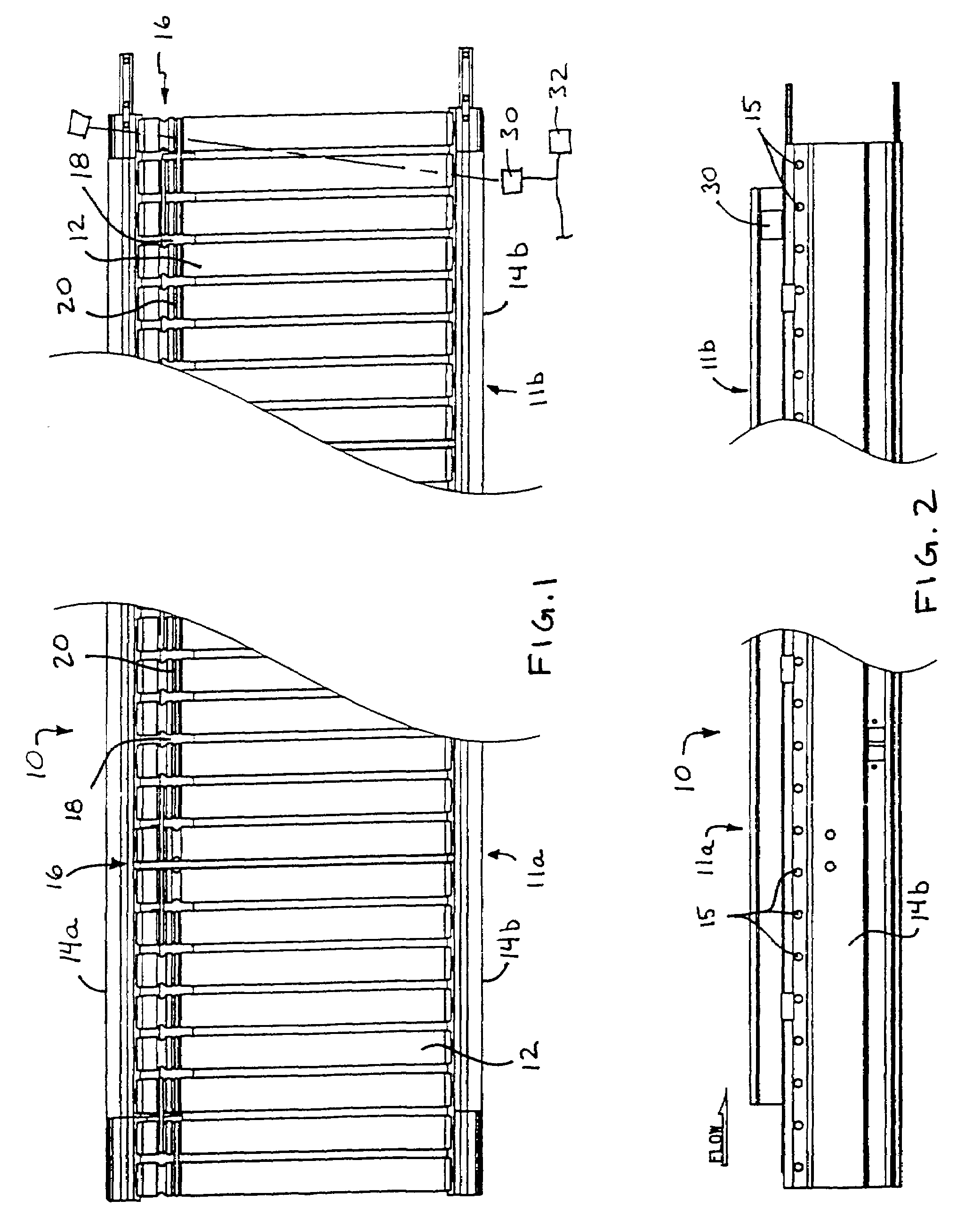
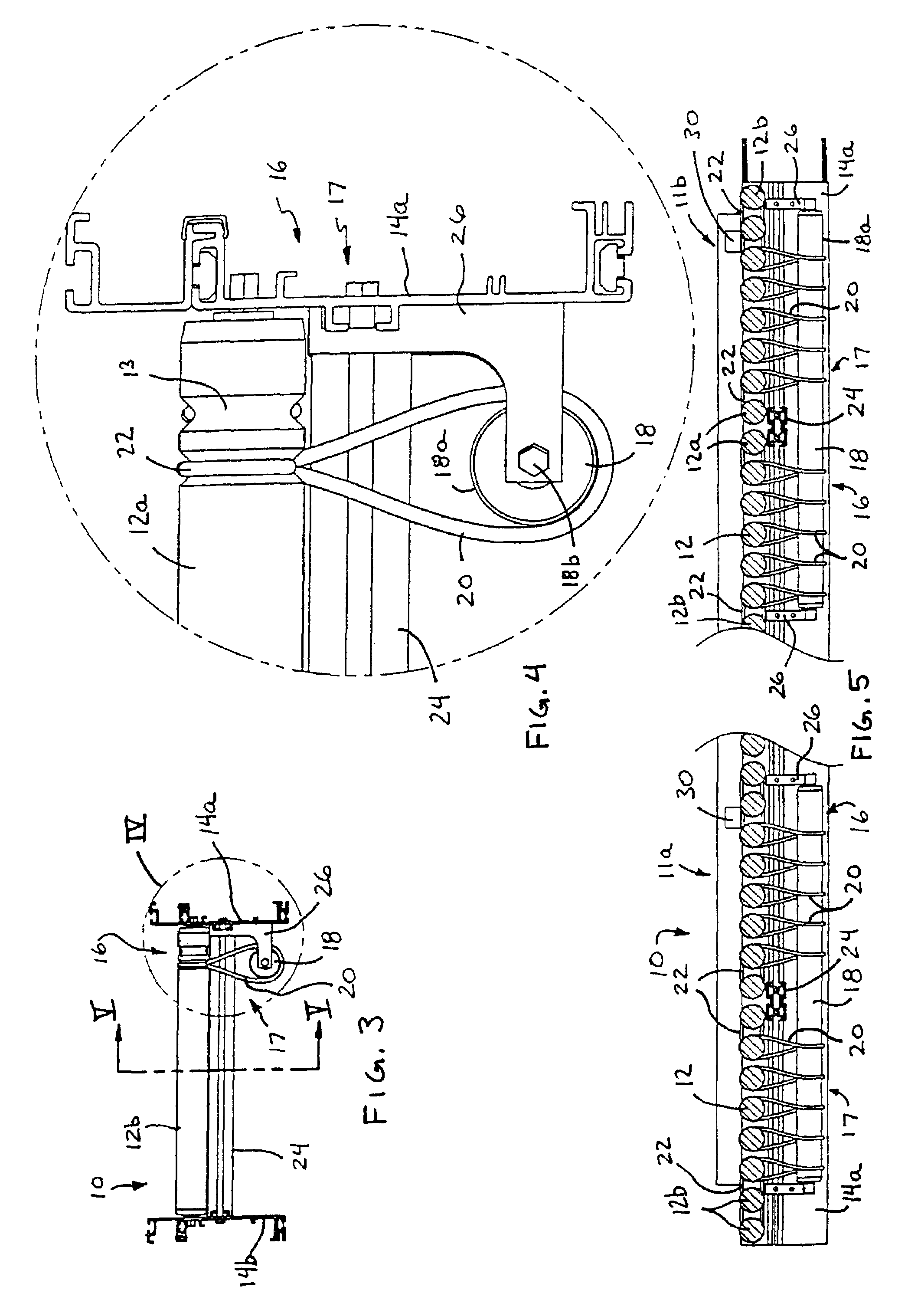
[0039]Referring now to the drawings and the illustrative embodiments depicted therein, a roller conveyor 10 includes a plurality of idler rollers 12 mounted to and extending between a pair of opposite sidewalls 14a, 14b, and a transverse drive system 16 which is operable to drive the rollers 12 of conveyor 10 (FIGS. 1-5). The idler rollers 12 comprise a plurality of idler or freely rotating or slave rollers and define a conveying surface of roller conveyor 10. As shown in FIGS. 3-5, transverse drive system 16 includes a motorized roller 18 mounted to and / or positioned generally along one of the sidewalls 14a, and a plurality of connecting members or drive members or bands 20 that drivably connect motorized roller 18 to the corresponding or respective idler rollers 12. As best seen in FIG. 5, roller conveyor 10 may comprise a zoned conveyor arranged in two or more tandem zones 11a, 11b, and transverse drive system 16 may comprise two or more transverse drive units 17. Each transverse...


PUM


Abstract

A roller conveyor includes a plurality of idler rollers positioned along and between opposite sidewalls and a transverse drive system operable to rotatably drive at least some of the idler rollers of the roller conveyer. The transverse drive system includes a motorized roller positioned generally transverse to the idler rollers and a plurality of drive members drivably connected between the motorized roller and respective ones of the idler rollers. Actuation of the motorized roller drives each of the drive members, which in turn independently rotatably drive the respective idler rollers. The transverse drive system may be selectively operable to accumulate articles on one or more zones of the roller conveyor. The roller conveyor may include a right angle transfer unit operable to transfer articles in a direction generally normal to the direction of conveyance of the idler rollers.

Description

CROSS REFERENCE TO RELATED APPLICATIONS[0001]The present application claims benefit of U.S. provisional application Ser. No. 60 / 492,497, filed Aug. 5, 2003, which is hereby incorporated herein by reference in its entirety.FIELD OF INVENTION[0002]The present invention relates generally to conveyors and, more particularly, to roller conveyors.BACKGROUND OF INVENTION[0003]Roller conveyors are known and typically include at least one powered or motorized roller and a plurality of idler or freely rotating or slave rollers. The idler rollers are driven via the powered roller and a plurality of O-rings or bands around adjacent rollers. For example, the powered or motorized roller may be positioned between two idler rollers and may be connected to and may drive the adjacent idler rollers via respective O-rings, while the adjacent idler rollers each may in turn be connected to and drive a second or adjacent idler roller via another O-ring, and so on along a zone or set of rollers of a roller...

Claims


Application Information

Patent Timeline
Patent Type & Authority Patents(United States)
IPC IPC(8): B65G47/10B65G13/02B65G13/071B65G47/54
CPCB65G13/071B65G47/54
Inventor TASMA, RYAN D.COTTER, DAVID H.EHLERT, RONALD C.
Owner DEMATIC
Why Eureka
Try Eureka